-
Welcome! The TrekBBS is the number one place to chat about Star Trek with like-minded fans.
If you are not already a member then please register an account and join in the discussion!
You are using an out of date browser. It may not display this or other websites correctly.
You should upgrade or use an alternative browser.
You should upgrade or use an alternative browser.
AndyP's Trek building thread
- Thread starter batboy853
- Start date

The modeling is impeccable. My only feedback for the video:
1. I wanted the torpedoes to be at least 2X to 3X faster.
2. There seems to be a complete lack of motion blur, which completely took me out of the scene. It’s funny — this seems to be something a lot of people miss, including professionals. The very first sequence in episode 1 season three of The Orville New Horizons features an epic flashback to the first Kaylon invasion of Earth, and somehow the artists at Muse forgot to flip the switch on motion blur. Completely took me out of the moment, because it was so glaringly obvious.
Other than that, I got nothing. I know I was entertained — nothing tickles my interior 12 year old more than a good space battle!!
@Professor Moriarty, I'll add it for the future, if I add motion blur it will be a very subtle motion blur. As far as the torpedoes, are you speaking of 2x-3x faster as in speed they fly away from the ship, or the speed at which they do the rotating flare effect?
@Santaman Thanks!!!
Today I remodeled the alcoves in the wall, for where the doors and aft stations are located. I feel it is closer now to the Experience set, than how it was before. I also tweaked the side wall panels so that the boarders are 1.5" thick. Originally I read the AI upscaled measurement as 1/2". It did not look correct. Added the alert status panels, and am re-using the alert status graphic I created for the Envoy Conference.
I also modeled the view screen, which I am still trying to get the dimensions right.
I just meant that the torpedoes looked like they were moving too slowly through space.
I just meant that the torpedoes looked like they were moving too slowly through space.
Maybe the torpedoes are going "First Contact" speed? IIRC, the E-E's torpedoes were fired at high sublight and took forever to miss the Phoenix.
I mean isn't the perception of speed all relative? I shall keep it in mind for next time 
So today I discovered that there was another reference image posted on the blueprint archive, which has a ton of legible measurements that I did not have previously. Today I started notating them on my AI enlarged overall blueprint. I will post it here once done.
What was nice, was that it had clear measurements of the view screen, and of the aft consoles. I corrected them on the set, will post pictures with next update.
Are you just using the Experience blueprints as a starting point or do you want it to look like the Experience bridge? If the former, keep in mind that they were drafted using the original pilot form of the bridge, and also altered for fire code and ADA compliance, so some things, like the ramp height, are different.
@Lt. Washburn: Using the blueprints as a starting point. However keeping the ramp height for now.
I would be curious about what some of the differences are, I knew about the ramp height, along with the addition of the exit signs, and the 21st century doors.
Also it looks like the prints I am using are from the tour, or the exhibition? museum bridge.
I would be curious about what some of the differences are, I knew about the ramp height, along with the addition of the exit signs, and the 21st century doors.
Also it looks like the prints I am using are from the tour, or the exhibition? museum bridge.
Last edited:
Looking good!
When I did the TNG bridge a loooong while ago, I also started with those blueprints to get the basic size right, but ignored them afterwards due to all the inconsistencies with photos of the sets.
The ceiling and especially the way it connects to the viewscreen area is different, as is the viewscreen "wall" as well. The tactical arch is also thinner, besides being shorter due to the lowered ramp. Of course the chairs are completely different too. I'm sure there were other, smaller changes, but I don't remember considering that was like 5 years ago at this point.
@Rekkert looking at pictures from the exhibition tour bridge the horseshoe seems to be total garbage. I remember at age 13 the being on the bridge at the experience, my dad took me on a trip there. I had unlimited access to the tour. I definitely went on both rides as many times as they would let me.
I actually referenced this image for building the horseshoe. but then modified it a bit to fit the smaller size of the ramp. Once I got the shape right I used the solidify modifier for the thickness. I'm not sure if I am happy with the wood material yet. It feels too much like marble.
I actually referenced this image for building the horseshoe. but then modified it a bit to fit the smaller size of the ramp. Once I got the shape right I used the solidify modifier for the thickness. I'm not sure if I am happy with the wood material yet. It feels too much like marble.
Updates since last posting:
Modeled the viewscreen, modeled the doorway to the head / conference room and begun texturing LCARS for the rear stations. For the rear displays I referenced the TNG Technical manual, and then as a shortcut, I utilized the filler graphics I created when I updated my Nova class bridge


Modeled the viewscreen, modeled the doorway to the head / conference room and begun texturing LCARS for the rear stations. For the rear displays I referenced the TNG Technical manual, and then as a shortcut, I utilized the filler graphics I created when I updated my Nova class bridge
Last edited:
Nice work keep it up. 


As the blueprints from the official set have been posted over at the blueprints thread, I am going to need some time to review, and possibly start over on a majority of this set. There are certain aspects that I think I can salvage, or reuse to save time, but I am kind of in a holding pattern and need to recharge my modeling motivation for a few days. I also need to decide on what all I want to remodel, and what can be saved. (I'm happy with things such as the helm and ops console, as well as the chairs on the set even though they are based on the experience versions)
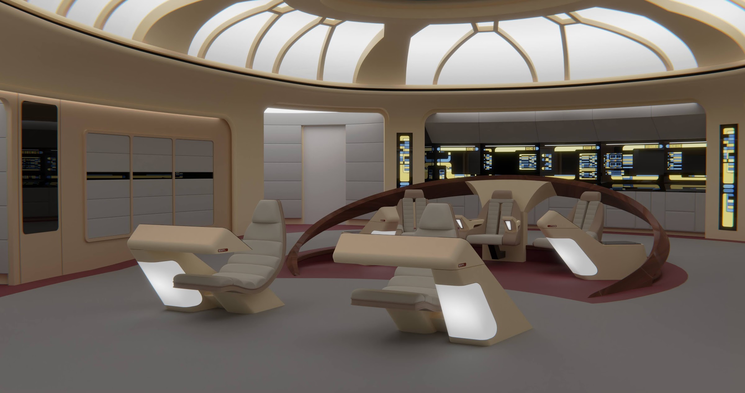
In the meantime I am working on LCARS for my Galaxy bridge V1 - the "eh... close enough" edition. Since last update: created the panels for the Helm / Ops consoles along with the display underneath it.

In the meantime I am working on LCARS for my Galaxy bridge V1 - the "eh... close enough" edition. Since last update: created the panels for the Helm / Ops consoles along with the display underneath it.
I've started working on Galaxy bridge V2 - "The hopefully more screen accurate version" using the blueprints posted over at the blueprints thread
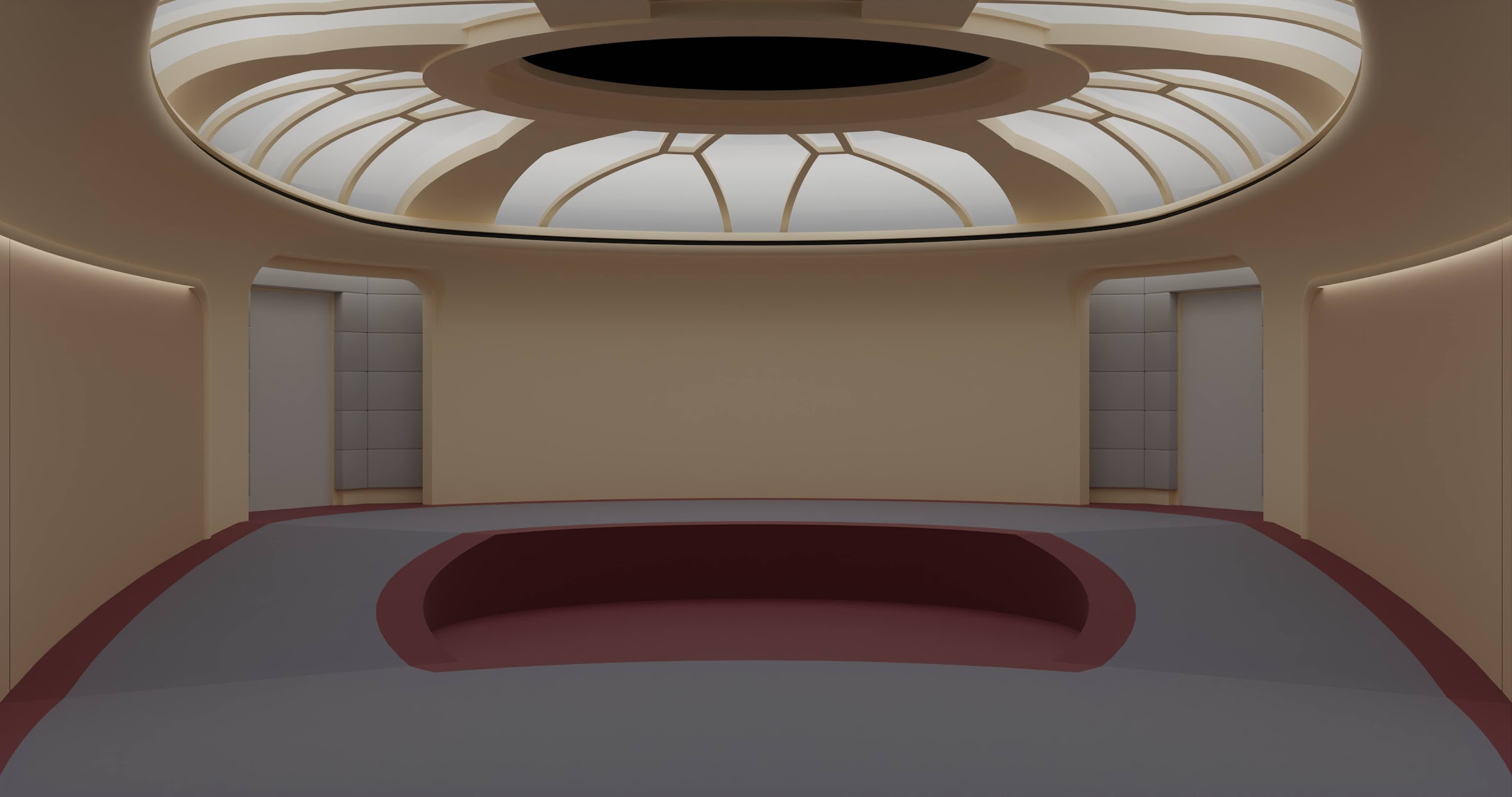
I think I might have already made a number of mistakes as the blueprints are not all to what the final set was. For example the upper walls curve to become more parallel near the view screen. I hope I have the curve in the correct location. I am also seeing a number of inconsistencies with measurements regarding the ceiling.
This image, shows the ceiling height should be 13', where as this image shows the the height should be 2ft + 6 inches above the walls, that are 10'9" in height, making it 13'3".
For now I have the height at 13' and I plan on redoing it later. The "ribs" I made using the same cookie cutters I used to make the v1 bridge, they seem to be the same between blueprints, but I am noticing that I have the smaller ribs too thick.

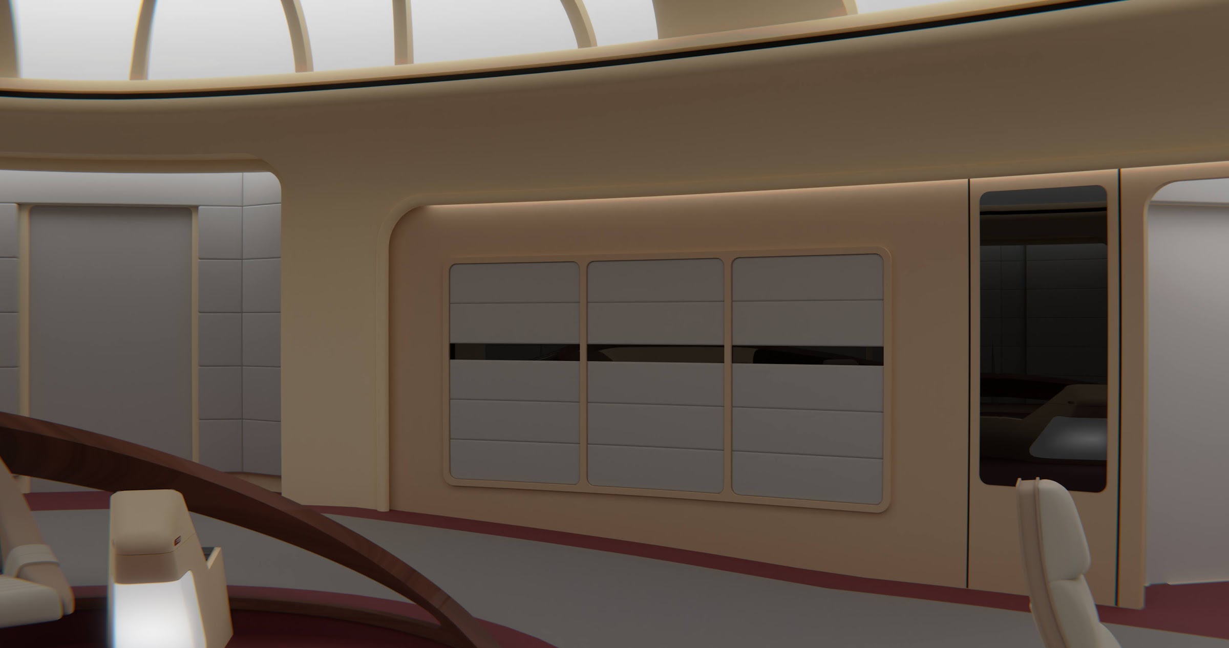
Another thing I am noticing is that I might need to fix is the height on the sides, struggling to describe what needs to be fixed so here is an image.

although, the generations version of the sides, would imply that the height of the upper portion of the sides should be 6'6" relative to the height of the upper level which would be +2' in height, so 8'6" from the lower level floor.
So long story short, progress made, but I think some of the work I've done this week will need to be redone to correctly match the set.
I think I might have already made a number of mistakes as the blueprints are not all to what the final set was. For example the upper walls curve to become more parallel near the view screen. I hope I have the curve in the correct location. I am also seeing a number of inconsistencies with measurements regarding the ceiling.
This image, shows the ceiling height should be 13', where as this image shows the the height should be 2ft + 6 inches above the walls, that are 10'9" in height, making it 13'3".
For now I have the height at 13' and I plan on redoing it later. The "ribs" I made using the same cookie cutters I used to make the v1 bridge, they seem to be the same between blueprints, but I am noticing that I have the smaller ribs too thick.
Another thing I am noticing is that I might need to fix is the height on the sides, struggling to describe what needs to be fixed so here is an image.
although, the generations version of the sides, would imply that the height of the upper portion of the sides should be 6'6" relative to the height of the upper level which would be +2' in height, so 8'6" from the lower level floor.
So long story short, progress made, but I think some of the work I've done this week will need to be redone to correctly match the set.
Last edited:
Similar threads
- Replies
- 42
- Views
- 1K
- Replies
- 23
- Views
- 905
If you are not already a member then please register an account and join in the discussion!