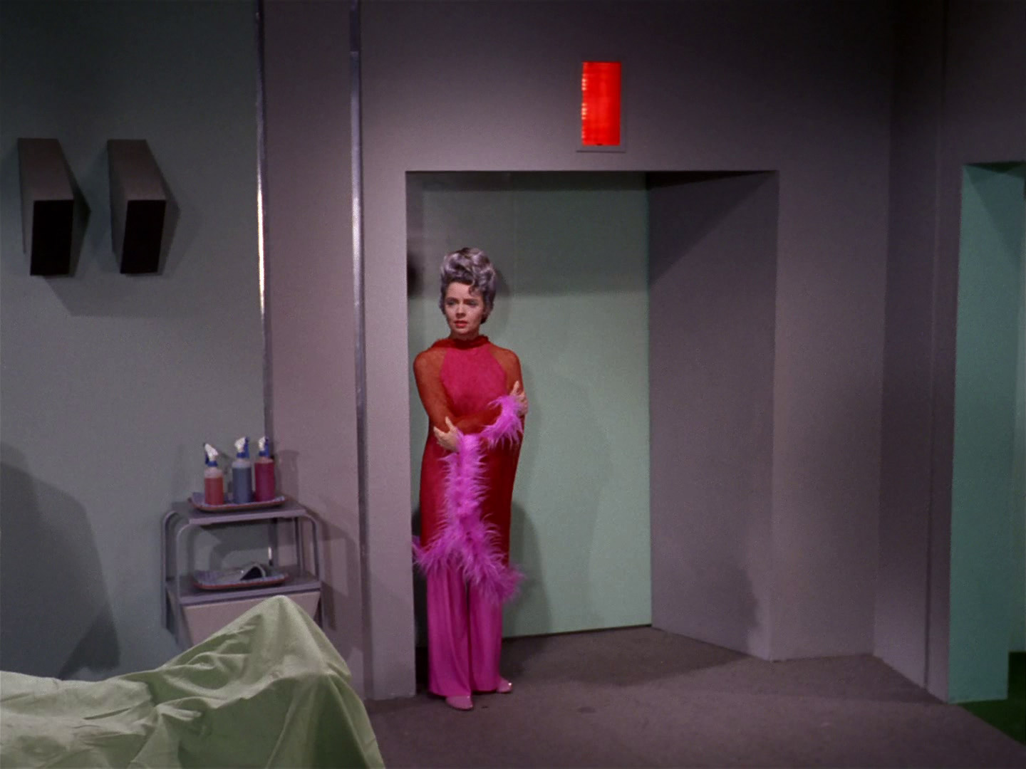
Yes, from Starbase 11.That room is on the Starbase isn't it?
-
Welcome! The TrekBBS is the number one place to chat about Star Trek with like-minded fans.
If you are not already a member then please register an account and join in the discussion!
You are using an out of date browser. It may not display this or other websites correctly.
You should upgrade or use an alternative browser.
You should upgrade or use an alternative browser.
New project - TOS Enterprise 1341-foot version full interior 3D model
- Thread starter Toddard
- Start date
Yes, Starbase 11 I believe. It is not technically a part of my Enterprise project, but I had most of the assets already created and the rest of the set was fairly simple geometry, so I did this as a bit of a side project.That room is on the Starbase isn't it?
If that happens, it means you're guilty.Hope that center seat is bolted to the riser. I'd hate to sit down and take a tumble backwards!
No. Sometimes some of the Sickbay / Exam walls had different colors, but they could vary from season to season. Huh. Is the transporter room the only area that has a non-gray wall?
No. Sometimes some of the Sickbay / Exam walls had different colors, but they could vary from season to season. 
Any chance that's a lighting thing?
dJE
Speaking in-universe and conceptually here, wouldn’t it be likely that on a ship with advanced technology the colors of walls, doors, etc can be changed with the push of a button? I don’t think there could be much that would destroy the illusion of this taking place in the future as fast as somebody in Starfleet overalls putting a fresh coat on deck seven.
Some of the colors seen could then easily be interpreted as mere “screen savers” put in place on unused spaces. The unassigned palette is part of the crew morale protocol.
Some of the colors seen could then easily be interpreted as mere “screen savers” put in place on unused spaces. The unassigned palette is part of the crew morale protocol.
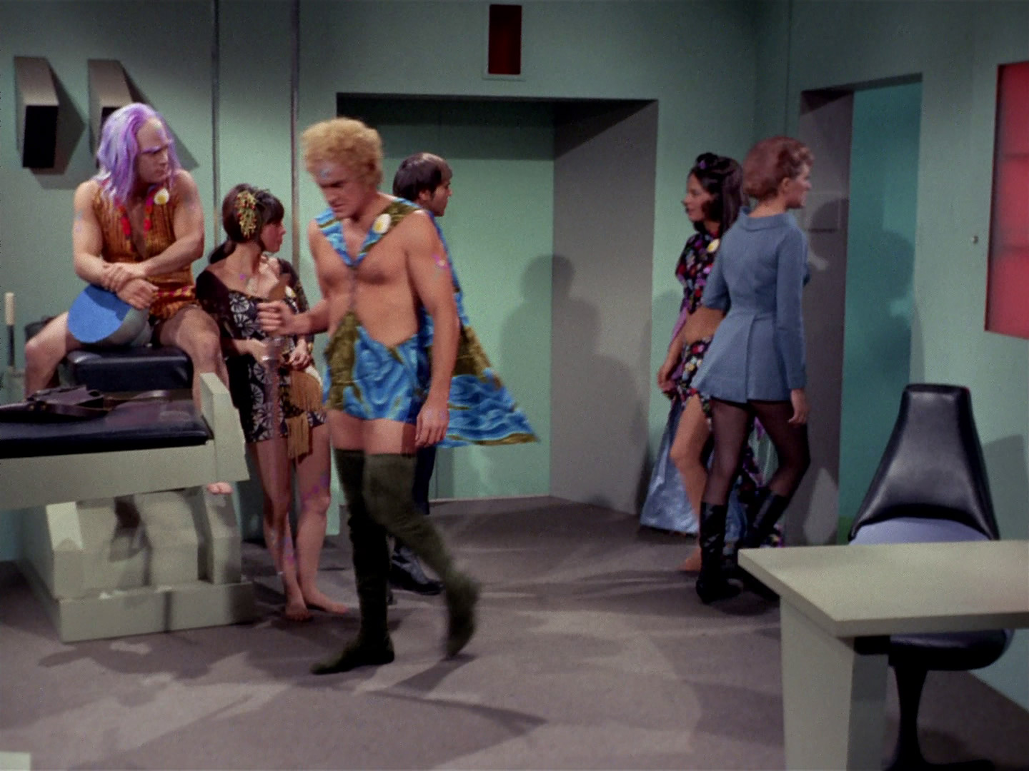
They used lighting to great effect in the series as an inexpensive way to change up the look of sets that were reused for multiple purposes (different crew quarters, Briefing Room configurations, etc.). But here's an example where I don't think lighting was used to change the color of a wall. Note the clean break between the gray wall and the blue medical status wall in the background.I'm pretty sure it's absolutely a lighting thing.
The wall on the left in this pic shows the same effect.
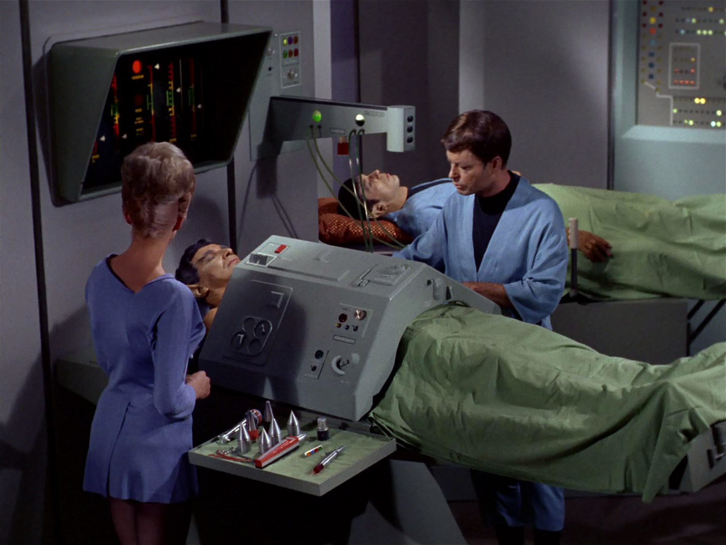
Here's an example where (again, in my opinion) both lighting and painted wall color were used. One might think the blue colored walls are strictly lighting, but if that were the case, I would think the blue light would spill over to the bedside viewers and bedframes, as well as the cast. The purple color seems an obvious lighting effect.
Yeah those walls definitely look like they were painted some kind of sage/sea foam greenish-blue. It's very subtle, and really only noticeable when placed next to the standard medium-gray walls.
Let's talk Turbo Lifts for a bit. Specifically, Turbo Lift maintenance. After zipping back and forth and up and down for hours, days, and weeks on end, they surely need a tune up from time to time. @Jim Botaitis has called out two of these maintenance areas on the Enterprise: one Deck 6 aft in the primary hull and one in the secondary. Here is my vision of how that might be done on Deck 6. This space is also used for Environmental Engineering (EE in the blueprint below) and general Engineering Maintenance Shops (EMS), so I may have to rearrange things a bit more once I start laying those to areas in.


The first thing you might notice is that even keeping just a few spare lift chassis around takes up a lot of space. This is exacerbated by the fact that I split up the lift cars into an inner hull and outer hull. I did this for more modular service, but I may have to rethink that decision if I want to have room for the environmental and general maintenance shop. Much credit goes to @Mytran for laying out the proportions and scale of the Turbo Lifts in this thread.

There are several unique features of this elevator area. First, the mag-rails (or whatever they would use) temporarily extend into the shop area so that the car can be picked up by a portable maneuvering arm. The crew might also use anti-grav devices, but handling may prove unwieldy since the car is only slightly less tall than the deck height. For this reason, the floor is recessed in this area to allow the car to be lowered a few inches before it is rotated around for service.

Here's a car all cleaned up and in final checkout before being returned to service. The floor will be assembled after the car is loaded up into the rails of the Turbo Lift shaft in the center of the room. A stack of ceiling and floor caps can be seen in the background on the left.

Three outer shells in a staging area, laid door-side down. The one in the foreground has been reconditioned. The two in back are waiting to be serviced. In my Blender file, I have sliders for wear and scratches to easily change the state of the parts.

A view from inside the shaft looking aft. From this spot, however, you'd find yourself dropping to Deck 9 pretty quickly. Some kind of safeguard would be needed to prevent someone from wandering in here, but I thought it was an interesting view.

A stack of caps and three internal shells in the staging area. Each car is assigned a number, seen here above the door opening, along with the stardate of last service just below.

Lastly, here is what the car may look like mid-rotation with a manipulator arm before it is moved to the working area. I still need to add the interior handles and the panels in the tall rectangular windows. Note that the opening does not extend through the exterior shell. I like the idea of the shafts having lights built into them so that you see your progress, so another point of rework might be to relocate the vertical rails forward to allow that.
ALSO: the elephant in the room is that the squared off corners in the front of the car don't allow it to rotate in the shaft. However, when the doors are fully open, they take up this space. I'm kicking around the idea of just making a cylindrical one-piece unit, with the doors serving as a locking mechanism once the lift is at its destination. That would allow the lift to rotate in the tube while travelling. The elevator doors would then become a structural / safety device first and ingress / egress method second.
Please let me know your thoughts about these ideas. I know there are plenty of issues with staging and logistics, and how all this would work. My brief time in a large welding shop at an earthmoving equipment manufacturer informs my ideas, but I'm certainly no expert.
The first thing you might notice is that even keeping just a few spare lift chassis around takes up a lot of space. This is exacerbated by the fact that I split up the lift cars into an inner hull and outer hull. I did this for more modular service, but I may have to rethink that decision if I want to have room for the environmental and general maintenance shop. Much credit goes to @Mytran for laying out the proportions and scale of the Turbo Lifts in this thread.
There are several unique features of this elevator area. First, the mag-rails (or whatever they would use) temporarily extend into the shop area so that the car can be picked up by a portable maneuvering arm. The crew might also use anti-grav devices, but handling may prove unwieldy since the car is only slightly less tall than the deck height. For this reason, the floor is recessed in this area to allow the car to be lowered a few inches before it is rotated around for service.
Here's a car all cleaned up and in final checkout before being returned to service. The floor will be assembled after the car is loaded up into the rails of the Turbo Lift shaft in the center of the room. A stack of ceiling and floor caps can be seen in the background on the left.
Three outer shells in a staging area, laid door-side down. The one in the foreground has been reconditioned. The two in back are waiting to be serviced. In my Blender file, I have sliders for wear and scratches to easily change the state of the parts.
A view from inside the shaft looking aft. From this spot, however, you'd find yourself dropping to Deck 9 pretty quickly. Some kind of safeguard would be needed to prevent someone from wandering in here, but I thought it was an interesting view.
A stack of caps and three internal shells in the staging area. Each car is assigned a number, seen here above the door opening, along with the stardate of last service just below.
Lastly, here is what the car may look like mid-rotation with a manipulator arm before it is moved to the working area. I still need to add the interior handles and the panels in the tall rectangular windows. Note that the opening does not extend through the exterior shell. I like the idea of the shafts having lights built into them so that you see your progress, so another point of rework might be to relocate the vertical rails forward to allow that.
ALSO: the elephant in the room is that the squared off corners in the front of the car don't allow it to rotate in the shaft. However, when the doors are fully open, they take up this space. I'm kicking around the idea of just making a cylindrical one-piece unit, with the doors serving as a locking mechanism once the lift is at its destination. That would allow the lift to rotate in the tube while travelling. The elevator doors would then become a structural / safety device first and ingress / egress method second.
Please let me know your thoughts about these ideas. I know there are plenty of issues with staging and logistics, and how all this would work. My brief time in a large welding shop at an earthmoving equipment manufacturer informs my ideas, but I'm certainly no expert.
Exactly my thoughts. There's no reason to have housing for the doors within the car itself, especially with all the downsides you've mentioned!I'm kicking around the idea of just making a cylindrical one-piece unit, with the doors serving as a locking mechanism once the lift is at its destination. That would allow the lift to rotate in the tube while travelling. The elevator doors would then become a structural / safety device first and ingress / egress method second.
Plus, if it was good enough for the TMP travel pod...
")
I envisioned the doors helping lock the turbo lift in place once it reaches the station.
Here is a drawing I made to show my thoughts.

Here is a drawing I made to show my thoughts.
")
Round 2 of the Deck 6 aft area Engineering Maintenance section. I put the turbo lift door design questions on the back burner for now while I work on some other details. What other things might I put in this maintenance section? I have lots of room!

Looking aft on Deck 6. A portion is open to Deck 7's Engineering Section below.

The impulse reactors span both Decks 6 and 7.

Zooming in a little closer.
 I decided to go with anti-grav units to handle the maneuvering of the turbo lift cars.

The turbo lift handle maintenance workbench.

The angi-grav units can be stored in low power mode directly on the wall.

View from Deck 6 down to Engineering on Deck 7

Deck 6 has got a huge number of assets. Most is crew quarters, but there are also three rec rooms, a theater, and of course the Engineering areas to the aft.
Looking aft on Deck 6. A portion is open to Deck 7's Engineering Section below.
The impulse reactors span both Decks 6 and 7.
Zooming in a little closer.
The turbo lift handle maintenance workbench.
The angi-grav units can be stored in low power mode directly on the wall.
View from Deck 6 down to Engineering on Deck 7
Deck 6 has got a huge number of assets. Most is crew quarters, but there are also three rec rooms, a theater, and of course the Engineering areas to the aft.
New video is up! I do a deep dive into how I use Blender to model Star Trek TOS crew quarters based on Jim Botaitis' blueprints.
Please see the references below to learn more about the blueprints I used to create this model.
U.S.S. ENTERPRISE HEAVY CRUISER - Resized to be 1341 feet long from https://www.jbot.ca/space/1bhc.shtml
Other links:
My photo album: https://photos.app.goo.gl/7GMixSXvFgX8zERW8
My YouTube playlist: https://youtube.com/playlist?list=PLNJZ8Im3-EG6pe1v16AtGnEI27um_5XuX&si=c492gW4W7-lOVYji
It doesn’t look like there’s enough deck height to rotate the cars on their X (or Z) axis given the deck height and the height of the cars. Is the turbolift maintenance shop taller than one deck?
Great demo, love the improvements you've made since last time. It's great to see you recreate the ship in 3D.
New video is up! I do a deep dive into how I use Blender to model Star Trek TOS crew quarters based on Jim Botaitis' blueprints.
Please see the references below to learn more about the blueprints I used to create this model.
U.S.S. ENTERPRISE HEAVY CRUISER - Resized to be 1341 feet long from https://www.jbot.ca/space/1bhc.shtml
Other links:
My photo album: https://photos.app.goo.gl/7GMixSXvFgX8zERW8
My YouTube playlist: https://youtube.com/playlist?list=PLNJZ8Im3-EG6pe1v16AtGnEI27um_5XuX&si=c492gW4W7-lOVYji
Just a quick thought regarding the set design, which you mention at around 55 minutes - the square openings on the back wall of the cabin were not for the cameras to poke through, but originally supposed to be windows. I expect they were covered when it became apparent that they were not a good fit, size or location for windows in relation to the exterior of the Enterprise.
You can see them in Mudd's Women, Enemy Within and Man Trap after which they were always covered by those coloured panels.
These photos show the windows to be fully finished setpieces with rounded corners and the appearance of "double glazed" indents - far more than just holes in the wall.


While it's possible that the windows could also have been used as a "peep hole" for a camera, the equipment of the 1960s was quite large and filming would have been restricted to only a few tight angles.
Besides which, both the rear walls were designed to be "wild" - if the director wanted to shoot a scene from that direction they'd simply remove that part of the set!
In Amok Time this was done a couple of times and in Mr Spock's cabin we can even glimpse the side of the shelving block which should be impossible to see!


I designed the ceilings to be 10 feet high in this version (1341 feet long) of the ENTERPRISE. If the turbo-lift cars are 8 feet tall and 6 feet wide, then the maximum diagonal is 10 feet. I have drawn the cars with slightly rounded corners, so they "should" fit. This may still be a bit tight, but I think Todd mentions somewhere that the deck is slightly depressed along the track where the cars enter the maintenance shop.It doesn’t look like there’s enough deck height to rotate the cars on their X (or Z) axis given the deck height and the height of the cars. Is the turbolift maintenance shop taller than one deck?
Thanks for that insight @Mytran! I was racking my brain to find out where I had heard the bit about the cameras but couldn't find anything concrete. It was likely just speculation that I took to heart because at the time it made a lot of sense. But your pic from "Amok Time" makes it clear that they weren't shooting through a hole in the wall.Just a quick thought regarding the set design, which you mention at around 55 minutes - the square openings on the back wall of the cabin were not for the cameras to poke through, but originally supposed to be windows.
I have removed that bit from my video, although YouTube says it will be about an hour before the vid is updated for all to see.
Similar threads
- Replies
- 25
- Views
- 10K
- Replies
- 87
- Views
- 20K
- Replies
- 482
- Views
- 59K
- Replies
- 192
- Views
- 28K
If you are not already a member then please register an account and join in the discussion!