Could you make two arrays of 32, each instances of the first within each array, and make the second ser short? I know I'm oversimplifying, but you get the idea.
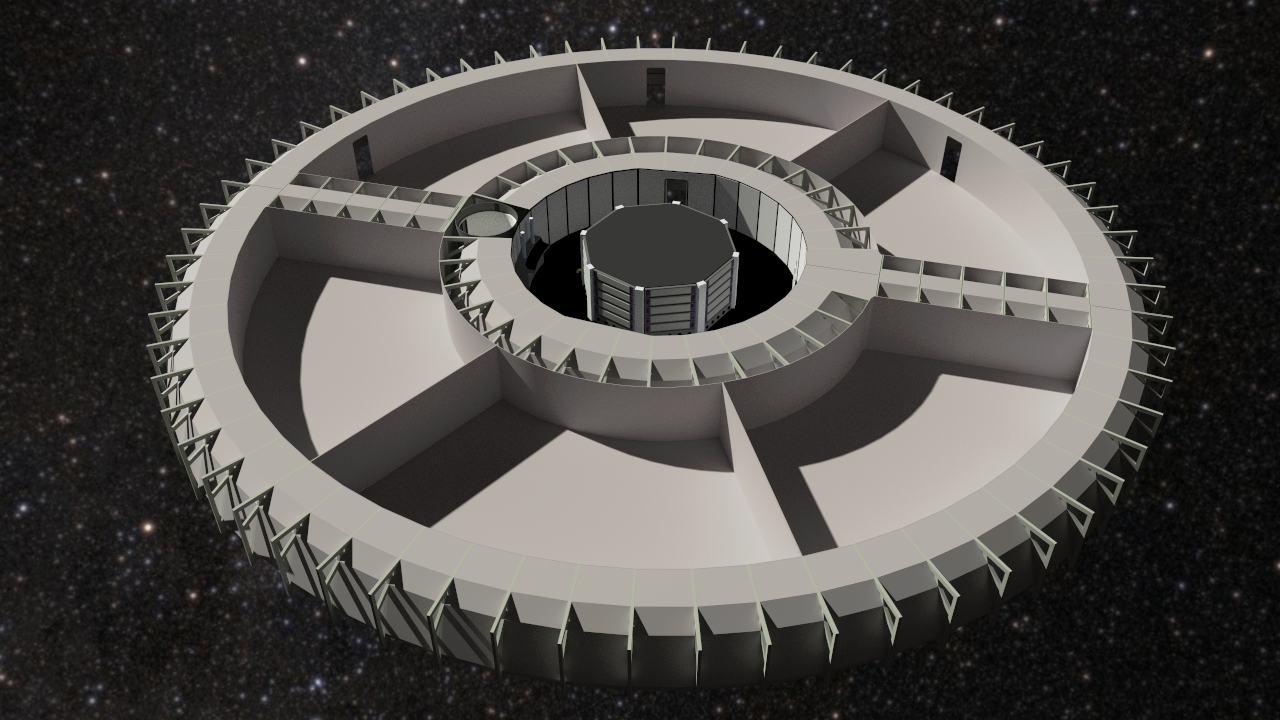
Yeah, that's a good idea actually. It's easy enough to do and I can tweak the alternating 4' and 8' sections to fit the available space. I just need to see how well they line up with the girder structure.I'd do them as 192 segments: then you get 64 "double-length" segments and 32 "single-length" segments. I'd expect it to then be simple enough to do two interlocking arrays...dJE
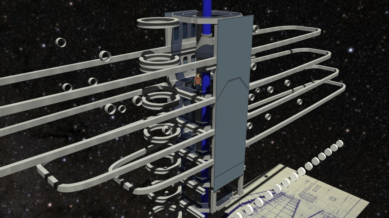
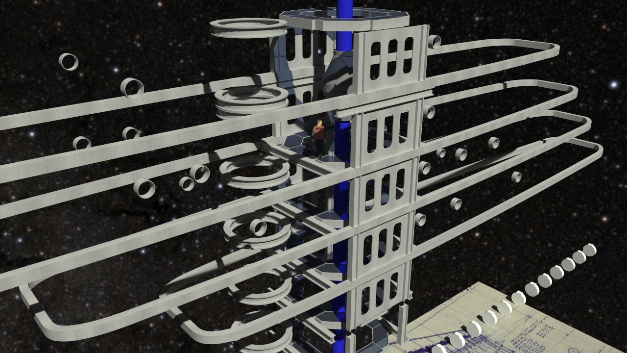
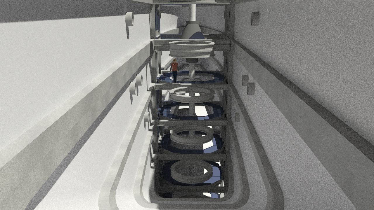
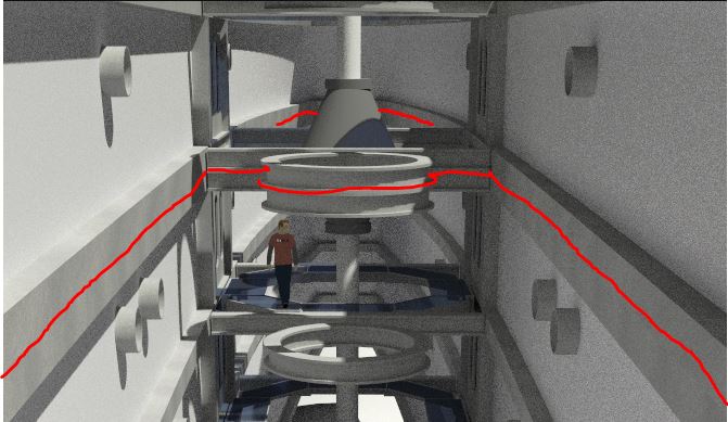
I'm adjusting it dynamically on a per-deck basis, so there shouldn't ever be a section longer than 8 feet. Right now on C Deck the actual measurements look like the below, and you must have a good eye because the outer ring segments are almost exactly 6'!Are you planning to keep the 64 piece segment on the other decks? The reason I ask is the segments currently look around 6 feet in length, which could lead to some rather large corridor sections on the outer edges of the saucer...


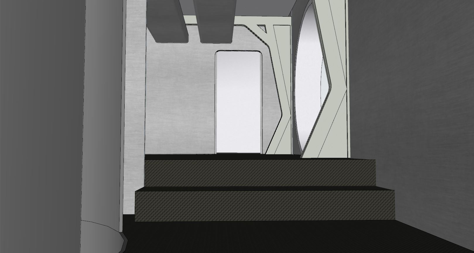
The other benefit of using equal length sections is that it everything fits together smoothly, and you have more freedom in door placement. Here's a render of C Deck so far;


")