• Welcome! The TrekBBS is the number one place to chat about Star Trek with like-minded fans.
    If you are not already a member then please register an account and join in the discussion!

Where'd This Phase II Cutaway Come From...?

Well, it depends how you want to look at it.

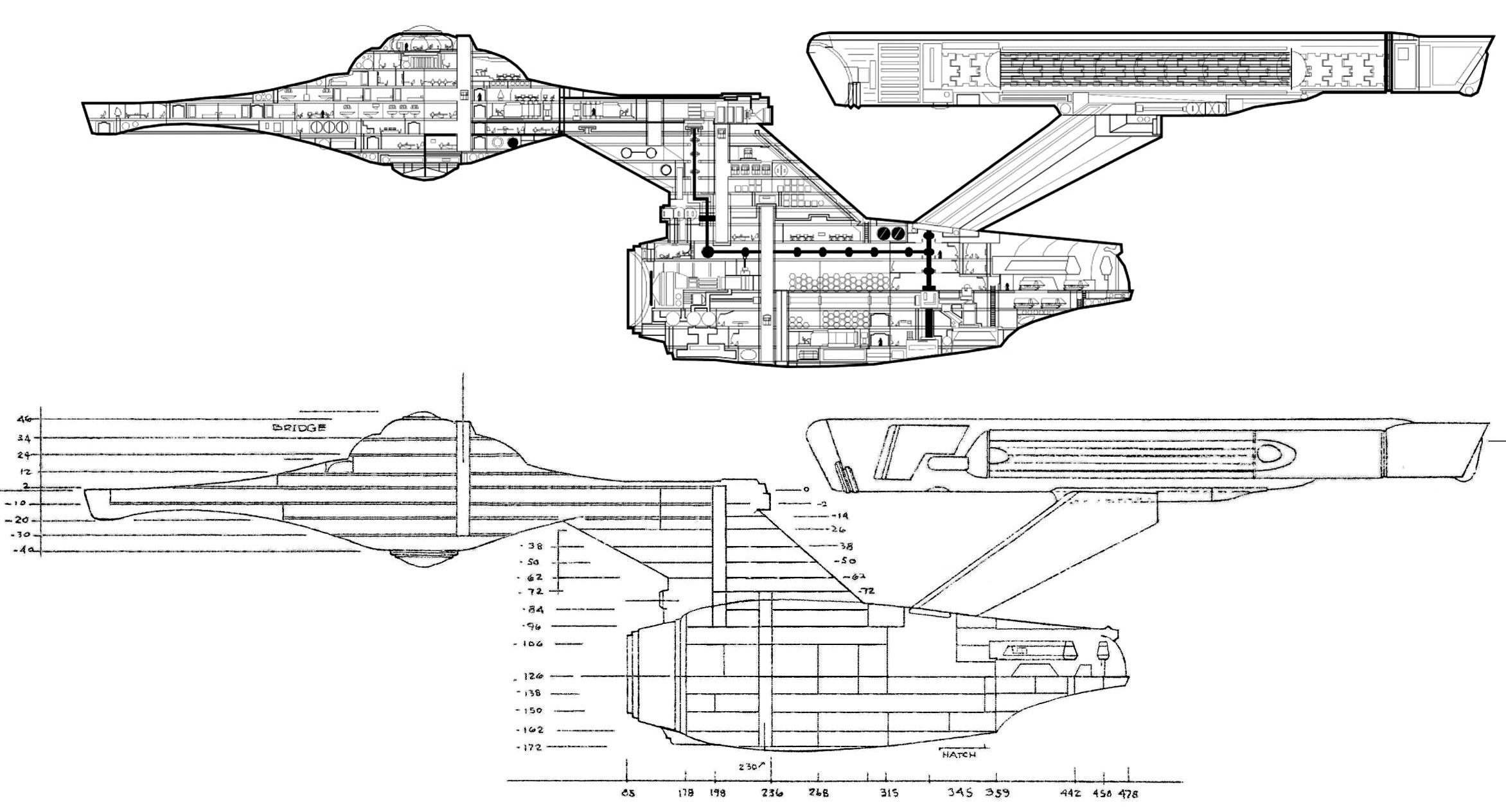
Since Mr. Jefferies suggested that this Enterprise was almost the same as the original, with changes to "struts and power pods only," we might assume that what we're looking at his his intentional effort to revise some aspects of the original design. Now, we know there were a few other cosmetic changes, such as to the bridge module with the addition of another turbolift, and the apparent addition of visible airlocks, and it's certainly possible (and perhaps likely) that the vertical core was also a change or addition.

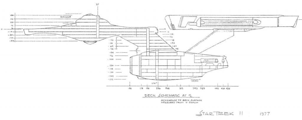
Still, there are some distinct changes to deck spacing here that seem to normalize and make more regular certain features shown in the famous Writer's Guide/TMoST cutaway.

If the vertical shafts are indeed power shafts rather than turbolifts, then I could see one engine room directly ahead of the impulse engines, with the vertical shaft being a power conduit leading down through the neck, then horizontally "jumping" aft to another vertical shaft, which the Phase II engine room would be oriented around, and probably the TMP-style horizontal shaft going back to the struts. Since both of these features were present in the TOS cutaway, we should probably assume that this was then unchanged from TOS to Phase II.
 
Phase2_MJ_cutaway_zps9be2fad7.jpg


What always jumps out at be in this drawing is the lack of a forward wall above the observation gallery of the hangar deck. A room above the gallery open to the hangar? Now what do you suppose that's for?
 
Phase2_MJ_cutaway_zps9be2fad7.jpg


What always jumps out at be in this drawing is the lack of a forward wall above the observation gallery of the hangar deck. A room above the gallery open to the hangar? Now what do you suppose that's for?
Strike that...from another thread...

....Here are a couple of details from the original:

MJsPhaseIICSDetail1_zpsf6cb0a20.jpg~original


MJsPhaseIICSDetail2_zps7a6acfa7.jpg~original


As you'll note, the engineering section is actually labelled. Also, the hangar features more original detail. Finally, there is a legend that gives the precise coordinates for Engineering, Hangar Deck and Shuttlecraft Storage and Maintenence.

Notice especially that the deck in Engineering is called out as 2 feet lower than the hangar deck (which is on the centerline of the hull). One final item of note is the elliptical profile of the hangar doors. An interesting detail, that.

M.
 
Interesting comparison of the two. The blueprint showing the entire ship features different detailing in the engineering hull's stern compared to the enlarged section close-up that's obviously from a revised or previous draft.

Bob
 
Interesting, since he labels the section below the nacelle struts as Engineering, is that where he envisioned the placement of the vertical warp core thing that was constructed for Phase II? The drawing has other shaft-like features, but I had the impression that those were the turboshafts. Though AFAIK, the phase II engineering set did not yet have the forced perspective horizontal shaft that was later added for TMP,
 
That's always been my assumption - and you're correct, there was no forced perspective segment. I believe there was, however, a glowy grille. The core itself was also of a somewhat different design.
 
I don't know who drew that graphic, but it is nicely done (and shows that the artist did his/her homework, which is nice to see). For those wanting to compare it to Jefferies' cross section, here are both at the same size...

 
Thanks, Shaw.

That blew up pretty good. I think the amount of research has lended itself that it makes tons of sense as an interpretation of Mr. Jefferies' cutaway.

Anyone notice the turbolift storage/repair facility in the neck? That's neat. I also like how the deflector machinery sits in the floor of a large, open bay, presumably for inspection.
 
That's wonderful, now we get a better and more detailed look at the blueprint from the first page of this thread. :techman:

Interesting how the talented artist apparently connected the antimatter pods to the Mike Minor intermix shaft.

I just don't get the "detour" of the power line near the photon torpedo launcher, I thought there'd be enough space between the launch tubes.

Bob
 
Perhaps they were erring on the side of caution, to not have it too close to the forward end of the dorsal?
 
I just don't get the "detour" of the power line near the photon torpedo launcher, I thought there'd be enough space between the launch tubes.

A couple of thoughts:

- That space is probably needed for access/maintenance of the the torpedo launch machinery.

- Probably a Bad Idea(tm) to put your main power conduit to the primary hull right between two of the most potentially dangerous items in the ship. If there were a premature detonation (even a partial yield) of a torp in one of the tubes, you're screwed.
 
Another thing to keep in mind is that the horizontal intermix shaft passes behind the center line turbo-lift shaft, which suggests (to me) that the artist is also going by an early concept sketch by Probert (I think) which shows two power feeds running along the space there and meeting just below the torpedo bay at the base of a vertical dorsal power shaft?
 
Also, in Phase II those aren't torpedo tubes, that was the phaser assembly. That feature was modified into the torpedo tubes for TMP.

In Phase II phasers acted like both beams and energy packets (like in Balance of Terror). The feature was added to give a physical location on the miniature for the effects people to work with as this was an issue during TOS (where the Enterprise miniature had no physical weapons visible). One of the biggest shortcomings I've seen with people attempting to complete the Phase II design is attempts to add features that Taylor and Probert came up with for TMP.
 
So nobody has been able to verify its authenticity? It is astonishingly clean and detailed.

My vote is fake, however. It doesn't appear to have a bowling alley.
 
Also, in Phase II those aren't torpedo tubes, that was the phaser assembly. That feature was modified into the torpedo tubes for TMP.

In Phase II phasers acted like both beams and energy packets (like in Balance of Terror). The feature was added to give a physical location on the miniature for the effects people to work with as this was an issue during TOS (where the Enterprise miniature had no physical weapons visible). One of the biggest shortcomings I've seen with people attempting to complete the Phase II design is attempts to add features that Taylor and Probert came up with for TMP.
True...so a true-to-Jefferies Phase II ship should have no TMP style phaser blisters.
 
Fascinating, I'd never realized those were going to be phasers. Love the guy EVA'ing in the image you linked, Bob. :rommie:
 
I wonder if the TMP bit about "increasing phaser power by channeling it through the main engines" was a left-over artifact of the idea that the phasers would be relocated to that site?
 
^^ Good point! Also, isn't it the general consensus that the "blister" on the bottom of the "sensor dome" of the TOS ship was originally intended to be a weapons turret?

Perhaps the only reason MJ added phaser blisters to different locations in his TMoST diagram was because the SPFX guys screwed up?

Fortunately, dialogue in various episodes supports multiple phaser/torpedo placements, so everything is covered.
 
Last edited:
If you are not already a member then please register an account and join in the discussion!

Sign up / Register


Back
Top