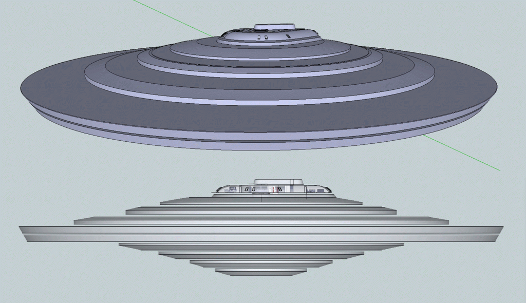
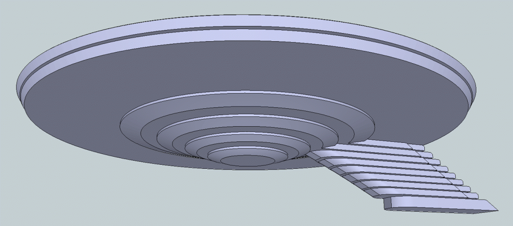
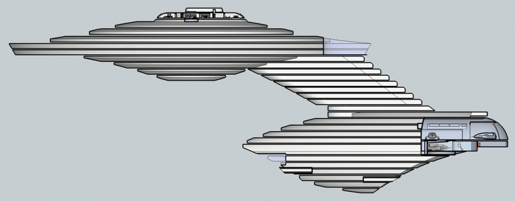
I've just been reflecting on the fact I've never fleshed out a design to this extent before. Yes, my TOS shuttlecraft drawings were similar, but that was one small craft and nowhere near this complex. Doing it in 3D is a help. In 2D you work on one view at a time which might later conflict with something in another view, which definitely happens. In 3D you can consider all sides at the same time which can prevent later possible conflicts. It can still happen, but I find less frequently and it's often easier to spot and fix.
With what I'm learning here I can see myself applying it to later designs as well as perhaps some of my earlier designs. Indeed I might even go back and use this to revisit my TOS shuttlecraft design. Regarding that shuttlecraft I think I will wait until the Round2 model kit is released and then I will have the benefit of using a product of Gary Kerr's work as a credible reference point.
Now that I have the decks laid out I’m going back to detailing. I still have to place the housing (or space) for the navigational sensor array at the bow of the saucer. I’ve just put the twin turbo lift shafts extending down from Deck 1 to Deck 10 in the saucer. From that I’ll plan where they'll extend aft along Deck 7 or 8 and then down the dorsal into the secondary hull. There is plenty of room width wise in the dorsal for the turbo lift shafts to run the same distance from each other as they are on the Bridge and down through the saucer (with 6 ft. or so to spare on either side) or I can put the two shafts immediately side-by-side to go down the dorsal and into the secondary hull. I think this is a better solution because it makes it easier to utilize the deck space in the dorsal more effectively. I’m also glad I have the room because having twin shafts allows for more efficient freedom of movement for the crew. If there was only one turbo lift shaft through the dorsal it would be more restrictive in terms of moving crew about the ship.
Another thought about turbolifts: except for the Bridge or the bottom decks in the saucer and secondary hull every turbo lift port tucks in off the main shafts, be they horizontal or vertical. This allows the computer to shunt turbo lift cars past access where another car might already be present. It’s rather like pulling onto the shoulder to stop to keep the roadway clear.
Before I start adding additional rooms I want the turbolift shafts in place to give me a clearer idea of where to place other rooms more precisely. I also want to give some thought to where the main companionways could be in the saucer, the dorsal and the secondary hull.


 .
.
