• Welcome! The TrekBBS is the number one place to chat about Star Trek with like-minded fans.
    If you are not already a member then please register an account and join in the discussion!

Refit/1701-A - 3D Model, Full Interior

Are you using a door width of 3 feet? While the majority of the doors on the Refit sets were 3 feet wide, the ones for the tubolifts on the bridge and in the corridors were slightly larger, at 3'4". At least according to my calculations. I missed it during my first build in 2014 and assumed they were the same width as the other doors. I ask because your doorways look suspiciously thin, and figured this info may help.

Ah that's interesting, at the moment they are indeed 3' wide. I was going off of this set plan, which was the only reference I could find:
bridge_4.JPG
 
Ah that's interesting, at the moment they are indeed 3' wide. I was going off of this set plan, which was the only reference I could find:
bridge_4.JPG
Yeah, I wouldn’t use that as anything more than a general guide. I’ve found that it’s not very accurate at all.
 
I've been experimenting with how to attach the viewscreen to the wall segment, and I think at a basic level this works pretty well. I've made the viewscreen quite CRT-like given the era the film was made. I know we have paper thin OLED's in 2019, but this screen is able to do holographic 3D projection... so that's what all the extra bulk is for ;)
(I have seen some debate about whether or not the TOS era screens are 3D, but at the start of The Search for Spock you can clearly see Kirk stood in front of a fully 3D starfield)

I've also added the EPS/ODN ports both beneath the screen and on top of the lighting panels. I'm going to make the cables 2" in diameter so they'e easier to see when the hull is turned off, which hopefully I'll be able to demonstrate soon :)

bridge_8.JPG
 
I'm amazed at how you could make a seamlessly multi-axial curve like this. Did you start with a wall cross-section, extrude it 360 degrees and then just slice it up, or is it something more complex?
 
I'm amazed at how you could make a seamlessly multi-axial curve like this. Did you start with a wall cross-section, extrude it 360 degrees and then just slice it up, or is it something more complex?

Essentially exactly that, yep. Apologies, this is going to be image heavy! :D

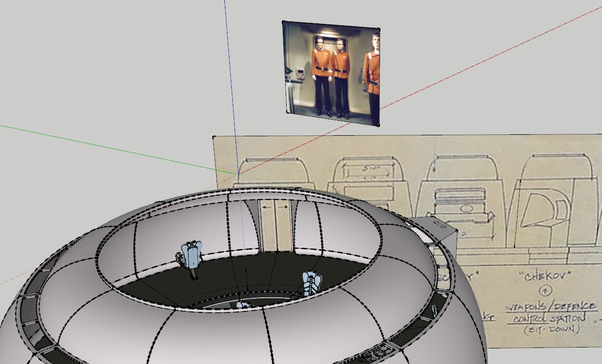
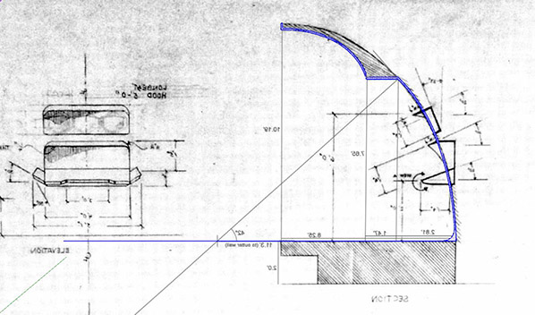
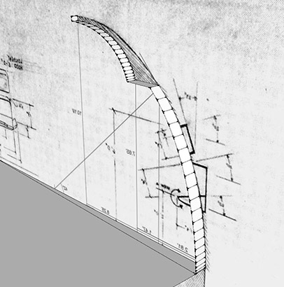
What I did in this case was take the only available plan I'm aware of, and drew the cross section on it like this:
sketchup_example_1.JPG


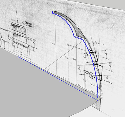
Then, I drew a circle for the desired bridge diameter (a little under 37'), and then copy-rotated the outline by one degree of that circle like this:
sketchup_example_2.JPG


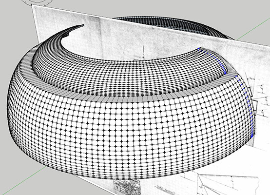
Then, because sketchup sucks at making faces, I join all the vertices together manually like this:
sketchup_example_3.JPG


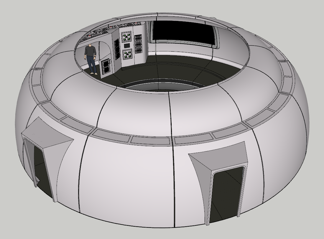
Next, I select everything and copy-rotate it in a full circle like this:
(after copying something in sketchup you can type *10 for example to perform that action 10 times automatically, so I only need to copy it once and let sketchup automatically do the rest)
sketchup_example_4.JPG


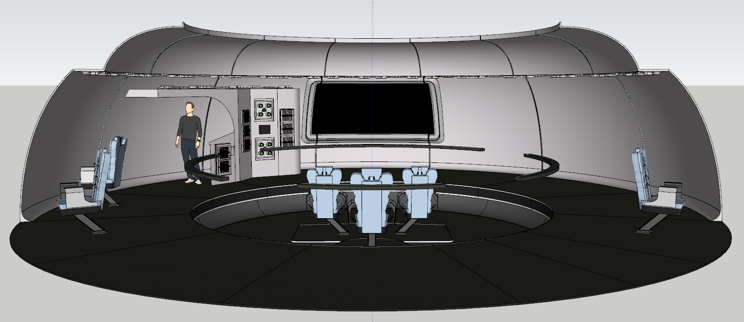
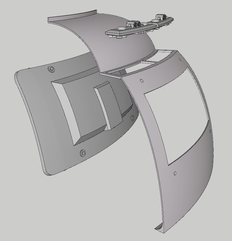
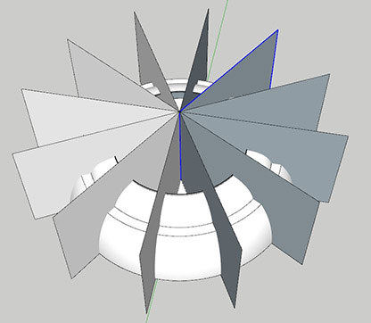
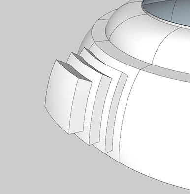
Now I can take some simple planes, one for each bridge section, and separate each one by 30 degrees like this:
sketchup_example_5.JPG


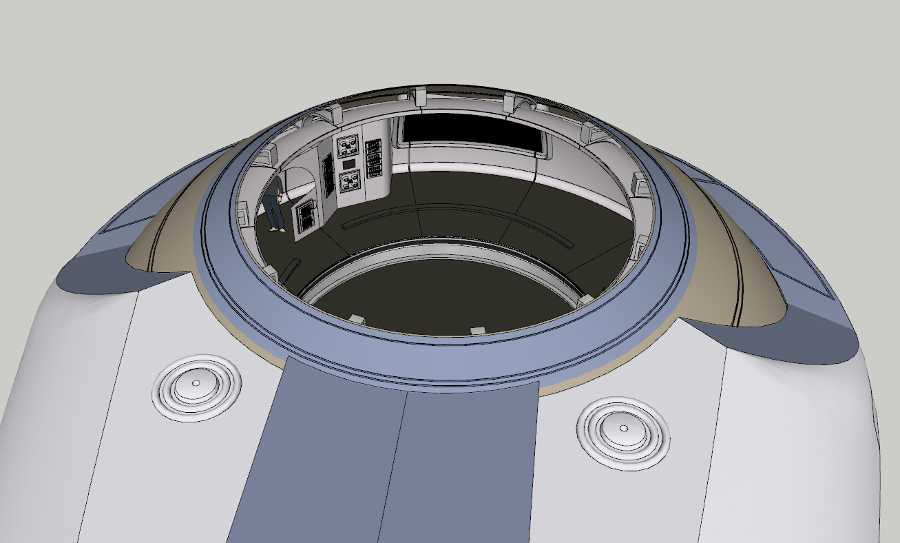
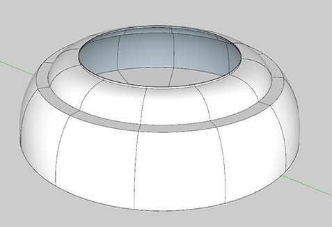
And finally, I can now intersect the solid circular mesh to create the 12 individual stations like so:
sketchup_example_6.JPG


That all took me about 5 minutes to make the basic geometry, but to make the more complex stuff I rely heavily on plugins. I can highly recommend any Sketchup user to get all the Fredo6 plugins, because they allow you to do stuff like extruding on curved surfaces, which is normally impossible in Sketchup:
sketchup_example_7.JPG


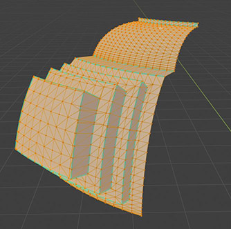
But all of that is only half of the work really, because getting these meshes into Unreal Engine requires a whole other workflow. Like, cleaning up the mesh in Blender and applying a face-weighted normals modifier, because Sketchup doesn't make very game friendly meshes:
sketchup_example_8.JPG


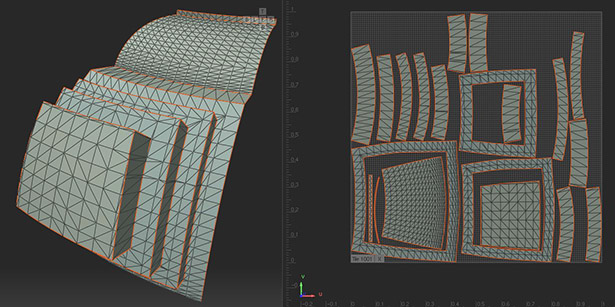
And then UV Unwrapping in RizomUV (both texture and lightmap UV's) because Sketchup also sucks at UV's :P
sketchup_example_9.JPG


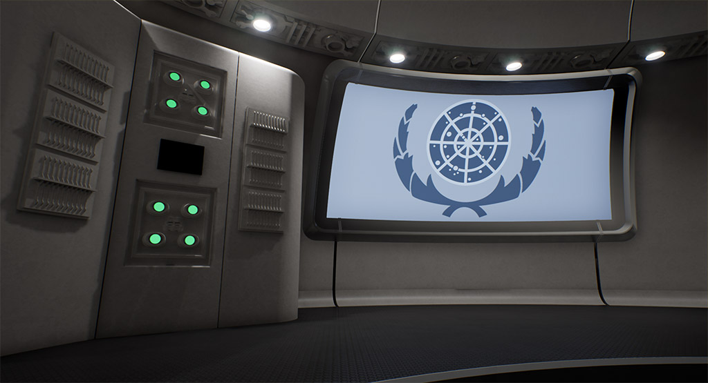
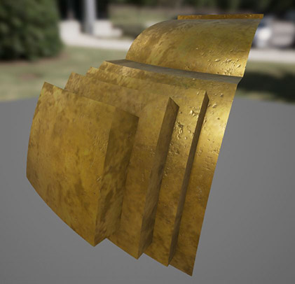
And then finally, after allll of that, materials and lighting can be applied in Unreal Engine:
sketchup_example_10.JPG


It's quite a long winded workflow, but I've found it's the only way to get half decent results when using Sketchup as the primary geometry creation tool for Unreal Engine :)
 
It’s beautiful! Although I’m shocked that you had to copy/paste all those little surfaces to make a full dome. That does seem like quite a thick slice of P.I.T.A. bread.
 
Wait wait wait... You're doing this in SKETCHUP?!?
Yep, it's actually really underrated. For ArchVis, which is essentially what this is, it's an ideal tool because of it's CAD-like nature. You just need to go through a few extra hoops to get the meshes game ready. I've tried using Blender for the whole process, but for ArchVis I find it simply can't match Sketchup for speed and simplicity.
I certainly wouldn't use Sketchup for any kind of organic modelling work though... that would be painful :P

Does sketchup not have a lathe function?
I'm not sure what that does :D
Basically Sketchup is really basic in terms of its capabilities, but there are numerous plugins which provide the functionality you'd expect from traditional modelling software. Without those plugins it wouldn't be fit for purpose.
 
Thanks for sharing your workflow. I can see why you'd want to use Sketchup over Blender for building interiors.

A lathe function can take your initial cross section and then rotate it around an axis to construct your cylindrical shape. The more rotations, the smoother it is so you could create each section 20 degrees at a time or do a full 360 and have a dome.

Still, very impressive with what you've built so far. :)
 
Yeah, as BK613 mentions the follow me tool will dramatically simplify your workflow for making spheres/domes and pipes if you're not already using it for that. Just draw an n sided circle (hit C and then type the number of segments you want) and then select the face you want revolved around that path, such as your bridge section, and presto! It'll generate the whole thing for you.

I'd also highly recommend curviloft if you're not using it already, it'll save you some time manually filling in faces between lines. Combined with something like curvizard, which autodetects line chains and welds them into a polyline for ease of manipulation, it makes creating a surface from two or more line chains into a pretty simple operation and enables some more complex organic geometry as well
 
Thanks for the pointers :D
It's funny you should mention the Follow Me tool, after making that post yesterday I actually remembered that feature exists and was like.. derp, lol

@WinstonSmith I've seen Curviloft before but never tried it. What I'd find really useful is the ability to select an abstract circular chain of lines and create a smooth organic face.
 
We all have those derp moments. :hugegrin: I spent years in trigonometry hell trying to use the three axes to rotate something before I learned to click-and-drag the Rotate and Protractor tools along an edge to set the axis of rotation.
 
Hahah yeah we all have those moments! I can't believe how many times I've discovered some feature and realised how much time I could have been saving hahah. You should definitely check curviloft out, it sounds like it'd do just about what you want. Here's a youtube video that shows some of its features
To view this content we will need your consent to set third party cookies.
For more detailed information, see our cookies page.
 
If you are not already a member then please register an account and join in the discussion!

Sign up / Register


Back
Top