• Welcome! The TrekBBS is the number one place to chat about Star Trek with like-minded fans.
    If you are not already a member then please register an account and join in the discussion!

Refit/1701-A - 3D Model, Full Interior

42902198924_d8c5f102ab_o.png

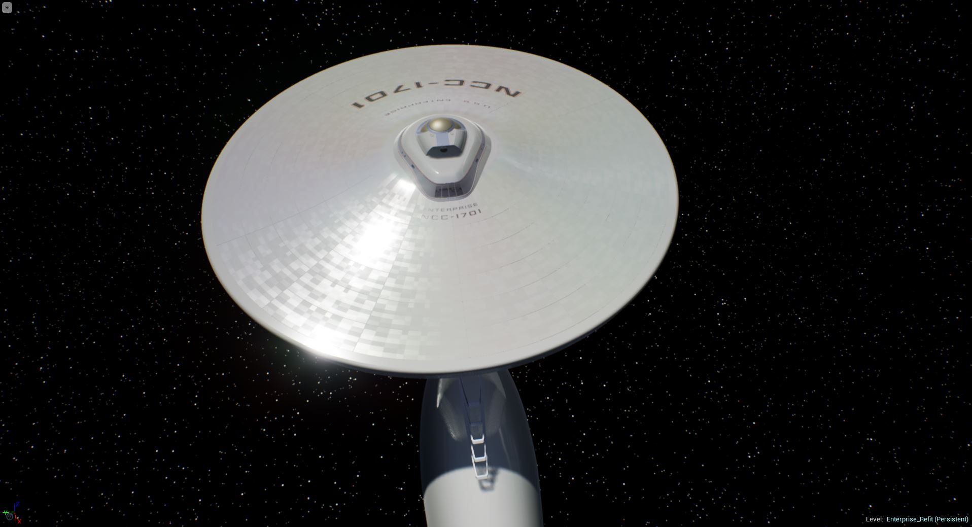
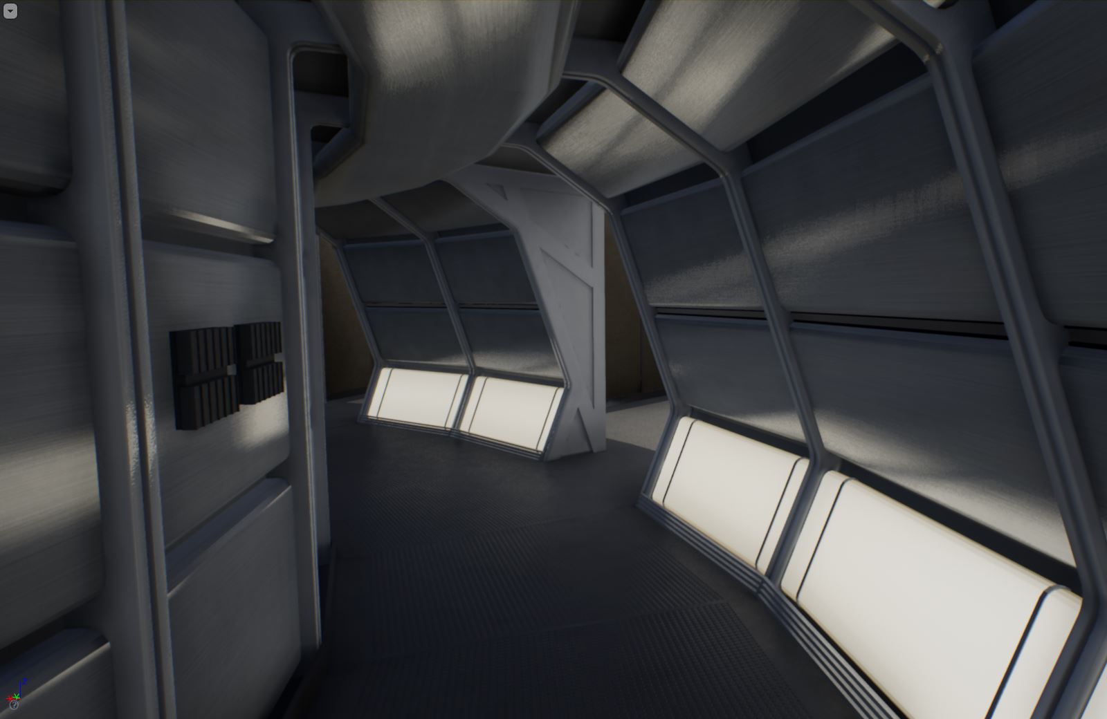
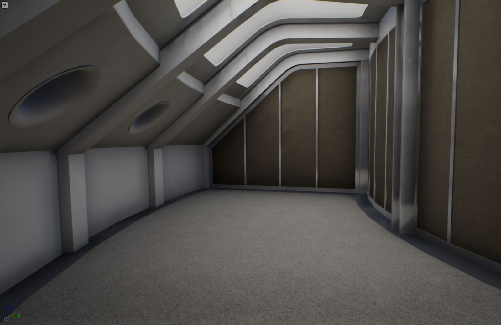
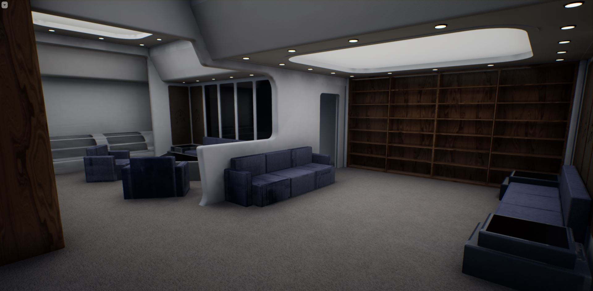
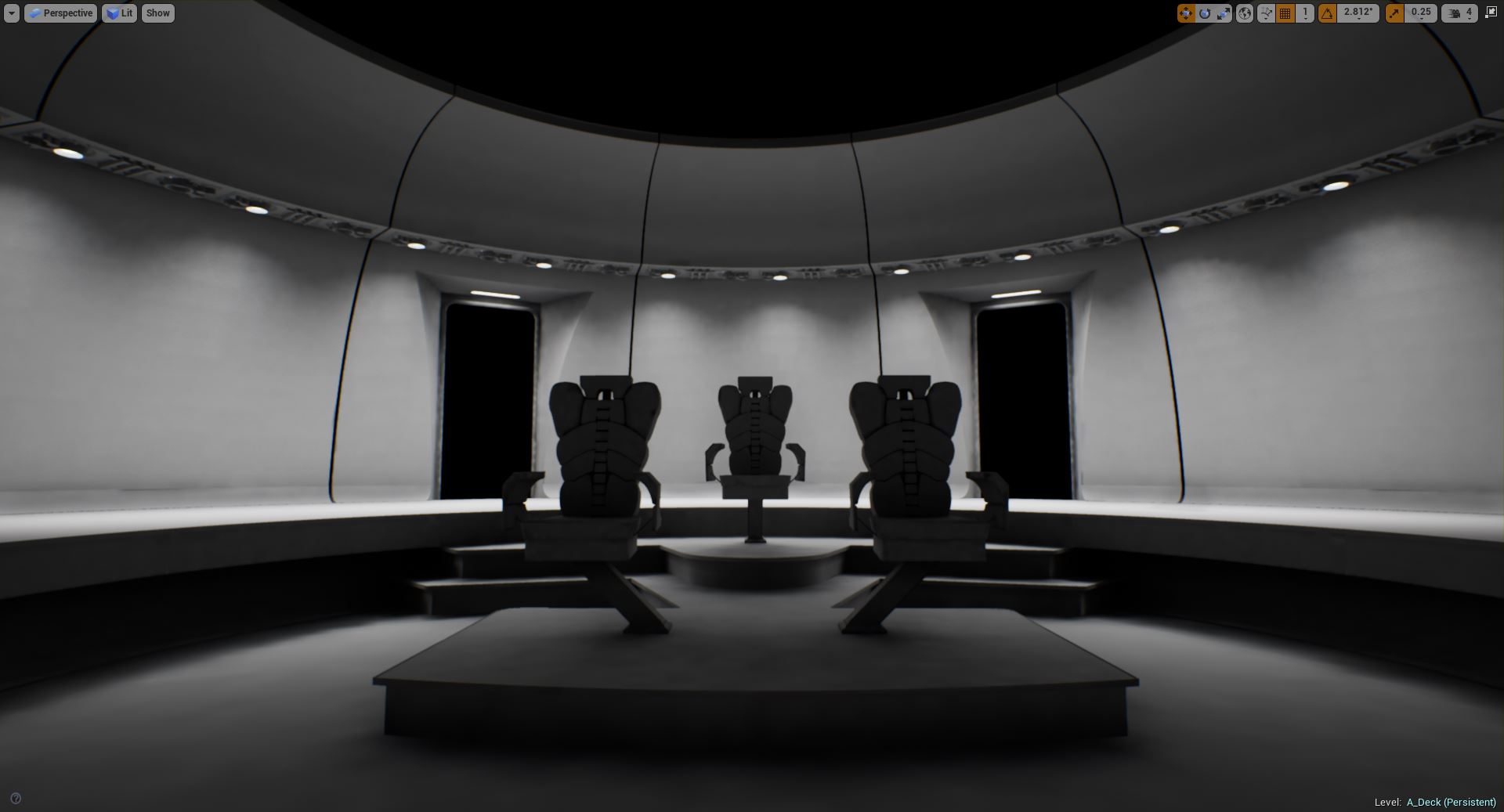
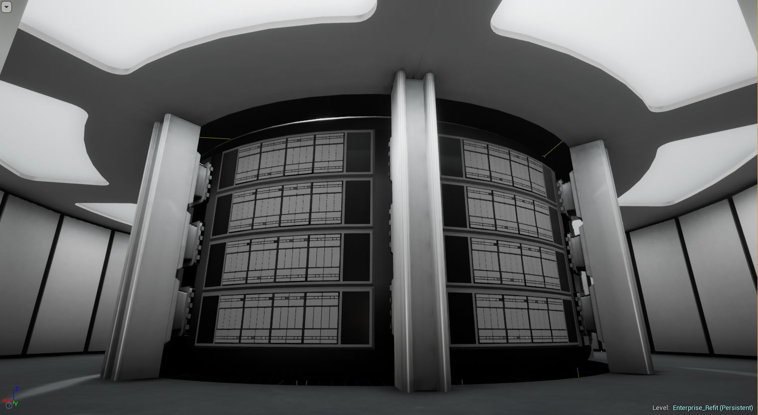
In the event that this may help you out, this is my 3D model for this area. You can ignore the interior. This is the only interior I have done and the only reason I did this one was that the windows are so big that something had to go behind there. The interior is an amalgamation of sources and invention. I don't assert any authority whatsoever on the interior.

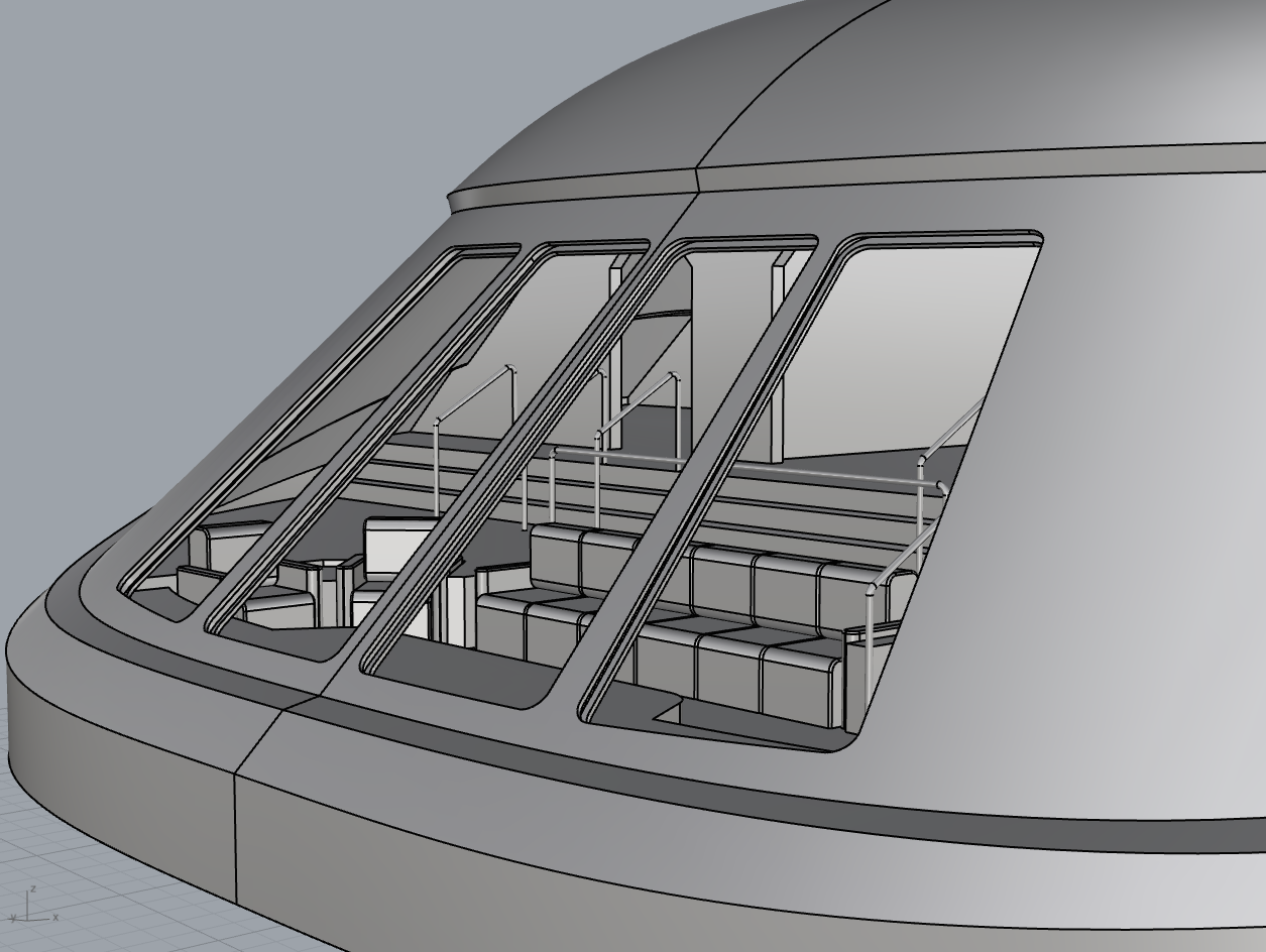
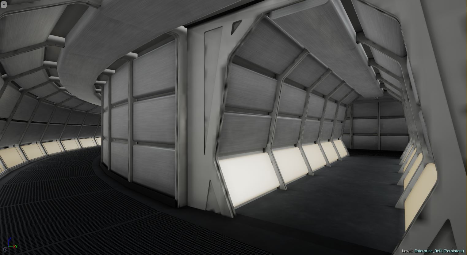
The two things that I may contribute here are the window frames and the inset shape. I have always drawn the profile as straight. I know a lot of sources show it curved. Yes, there appears to be a slight curve at the back of the inset in the studio model. I can't really tell if there is a curve at the front. From a side view, the outer profile is decidedly curved at the front. However, we are dealing with something that is fairly small, and a curve here might be just the result of handcrafting.

Not to pick on the model makers but, this area has a lot of imperfections. The various bevels are not consistent. I have tried curving the back and fronts slightly but my choice has been to make all the bevels the same width and the lines straight.

Hey, it's great to see you posting here. I've been using your plans almost exclusively to model the outer hull. Your detail to attention is fantastic.

The window frames are interesting, because I'd like for them to include some support beams but they're quite thin. I've been leaving that part for now until inspiration strikes :)
 
include some support beams but they're quite thin

Actually there are beams/ribs that run up on the inside face of those columns that go into (and are filleted into) the face of the of the lower seating-area lower back wall, as seen in the screencaps of the shuttle arrival (shown below lightened and outlining the column on the left in lime green):

officers-lounge-screencap-01.jpg


They are also present in the Ekker interior lounge blueprints:

ekker-lounge-002-beam-detail.jpg


Those would actually make those columns more robust than simply the thickness of the window frames. But because their cross section is a soft trapezoid you would have to be at looking at the windows from a very oblique angle to see them from the outside.
 
I've been using your plans almost exclusively to model the outer hull.

Glad someone can make some use out of them.

The window frames are interesting, because I'd like for them to include some support beams but they're quite thin.

Even the way that I have a recess for window pane, there is about 0.20" at the top (and a lot more at the bottom). That's nearly a 2-1/2" square beam in scale. That would be pretty hefty frame (even on a battleship) if were just embedded in the frame. Of course you can make it deeper so the frame is visible on the inside.

Off the top of my head, I'd throw out that maybe such beaming might be heftier in the center frame and at the outsides of the window group and less hefty between the pairs of panes.
 
As part of the great UV-unwrapping marathon I'm finding it easier to just remake some assets again from scratch, so today I completely re-did the computer core :D
It's not finished yet, but I'm liking the new version. I've also added telescopic brackets for holding the core in place, which when released retract backwards and allow the core to be removed.
enterprise_refit_computer_core_wip1.JPG


I've been facing a fairly steep learning curve when it comes to the UV unwrapping for lighting, because Unreal Engine is extremely fussy and if you don't do it perfectly you get all kinds of horrible blotches everywhere, like the dark patches on these arches:
enterprise_refit_corridors_wip5.JPG

It's such a sloooow process, but when it's done properly the benefits are huge in terms of visuals and performance.
 
Still looks very good @DanGovier :techman:

The blotches on the arches look like stepping resulting from a too small shadow map setting on the lights. But I'm not familiar with the Unreal Engine though so just ignore me if it doesn't apply to UE :)

That is exactly the issue yep. The shadow map (or lightmap as UE calls it) is only 128x128, so when you stretch that over the Arch mesh it becomes horribly pixelated. It looks fine at 1024x1024, but when you consider just how many archways there are, it eats a lot of memory so you need to keep the maps small. The trick is to warp the UV map so that there are absolutely no diagonal/curved edges, and also have it so that each edge of each UV island starts and finishes on the exact pixel boundaries. Kinda like this, for the same mesh:

Texture UV Unwrap:
uv_example1.JPG

Lightmap UV unwrap:
uv_example2.JPG


It means you have to do 2 unwraps for every mesh, and the Lightmap UV needs to be fiddled with a lot before it bakes nicely. Nightmare :P
Yep. I’ve made 2 uvs for every mesh I’ve generated for my many projects. It’s pretty easy once you get used to it, but with baking lighting you’re still gonna get shadow map artifacts here and there. There’s no perfect solution, unfortunately.
 
It's been ages since I updated this thread, but I've still been hard at work building scripts and materials :)
Here's a couple of shots of the latest progress:

Outer Hull
To view this content we will need your consent to set third party cookies.
For more detailed information, see our cookies page.
saucer_wip1.JPG


Corridors
Still not completely happy with the colour or light levels yet, but we're getting there :)
enterprise_refit_corridors_wip6.JPG


Briefing Room

This will contain a similar table to that seen in TOS, and the same console/display that we see in Kirk's quarters.
enterprise_refit_offices_wip1.JPG


VIP/Officer's Lounge

I've toned the "luxury yacht" look down a bit and made it more in line with the TWOK aesthetic. The chairs aren't rendered properly yet, I still need to UV unwrap them :)
enterprise_refit_officers_lounge_wip15.JPG


Are those angled light panels in the Briefing Room? Very reminiscent of the windows in Picard's observation lounge! :techman:
 
I have to say, I like that thought of the briefing room being on deck two, with those viewports looking out.

Will the conference table have that triangular multi-screen that was commonly seen in TOS as well?
 
@DanGovier, are there any updates on this project? It’s one of a few on here I can’t wait to see continue.

I've been laying low in the wake of the whole Stage 9 thing, but every now and then I add a bit more to this :)

My intention is to release regular videos from the perspective of an engineering study, looking at the various ship systems and how they all connect together etc. I'm not going to be releasing any more publicly available downloads for the foreseeable future though due to legal concerns.
 
So here's what I've been fiddling with recently. I've been inspired by @Donny 's latest efforts, and I'm determined to get this thing done! :D

bridge_1.JPG

bridge_2.JPG

bridge_3.JPG


I'm just using a plain white material for now while I build the geometry and get the lighting right, but hopefully I'll be able to start injecting some colour soon :)
 
Are you using a door width of 3 feet? While the majority of the doors on the Refit sets were 3 feet wide, the ones for the tubolifts on the bridge and in the corridors were slightly larger, at 3'4". At least according to my calculations. I missed it during my first build in 2014 and assumed they were the same width as the other doors. I ask because your doorways look suspiciously thin, and figured this info may help.
 
If you are not already a member then please register an account and join in the discussion!

Sign up / Register


Back
Top