Hello, all. It is me, the Ghost of Enterprise Past. Like Dr. Frankenstein I have come to resurrect this old, dead zombie project thread with some new life (with permission of course). I have brand new updates!

For the 2010 Ships of the Line Calendar, Doug Drexler decided to refit his Enterprise NX-01 with a new secondary hull. To be honest I didn’t particularly like the additions when I first saw them and had no intention of EVER doing anything with it. But over the last four years I have grown to like the secondary hull. After a lot of requests I have relented and decided to create deck plans for it. (Actually I missed working on the project too.) I am here to show you kids the beginning stages of my work. You know what they say, never say never, and I should have kept my mouth shut.
To start this new series I began with the key piece of hardware for the new section: the warp core. When he introduced the refit on his blog Mr. Drexler had made it very clear that the new hull contained an experimental secondary warp core. This core would supplement the primary core still housed in the saucer but would represent the next evolutionary stage in warp technology. The purpose of the refit hull was to act as a “test bed” for Starfleet’s latest technology.
You would think designing a brand new core would be exciting and fun but it has been rather stressful. Nothing is more daunting than a blank piece of paper. After six months of designing, redesigning, screaming, scratching, paper fires, sobbing, hysterics, and panic attacks, I finally came up with an idea that I liked. I wanted to create something that looked similar but was different while bridging the gap between Enterprise and TOS. I was also driven to incorporate a better flow with some of the technology. The most pressing issue for me was to make this warp core BIGGER. I always felt the core we saw on the show was not big enough to generate the power the ship needed. Needless to say there were a lot of variables to keep a handle on… and to drive me insane.
But enough chatter… here is what I have.
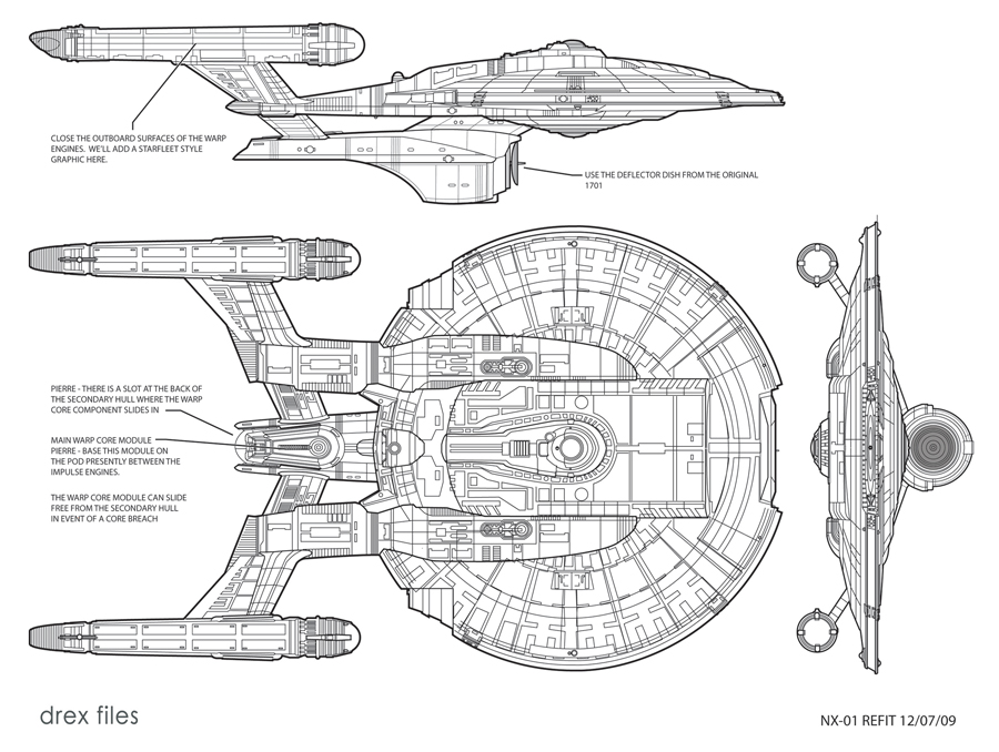
To get us started (and to refresh everyone’s memory) this is a copy of the plan that Doug Drexler put together to build the refit computer model.
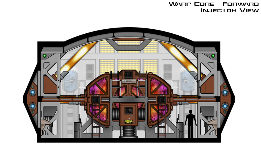
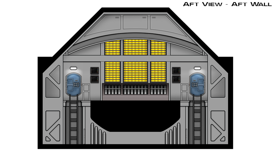
This is the new warp core. This view is from the forward section of the engine room looking aft at the front of the core. The core is about fifteen feet tall and twice the width of the original engine. If you look closely you will see that there is an upper level “walkway” that runs through the middle of the core. (The floor plan will describe this better.) The two “lobes” on each side are the deuterium injectors while the rectangular “box” under the gantry is the antimatter injector. The front of the antimatter injector pops open and slides out to allow access to the injectors themselves.
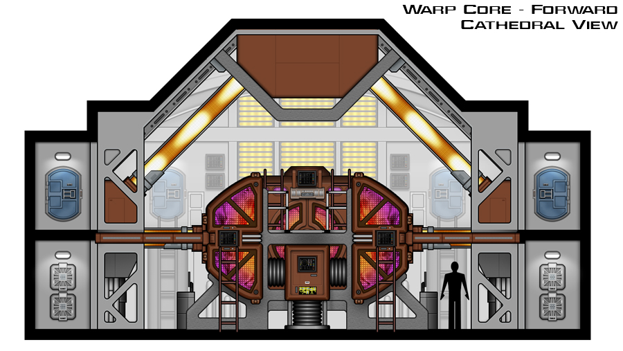
This is the same view but with the forward ceiling removed to reveal the aft cathedral. This area houses the plasma conduits that feed into the warp nacelles. Notice how it looks very similar to a certain set from TOS?
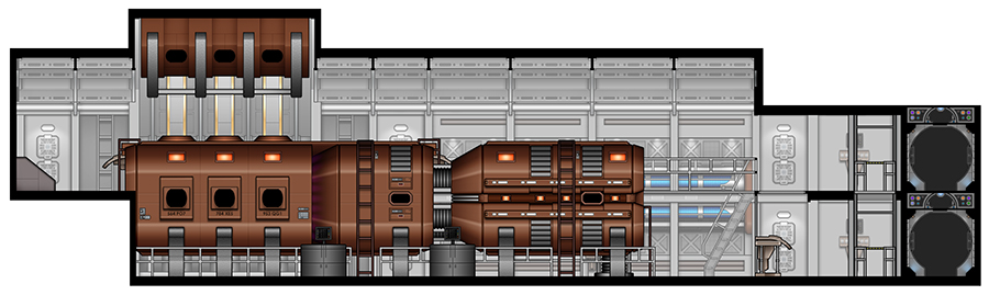
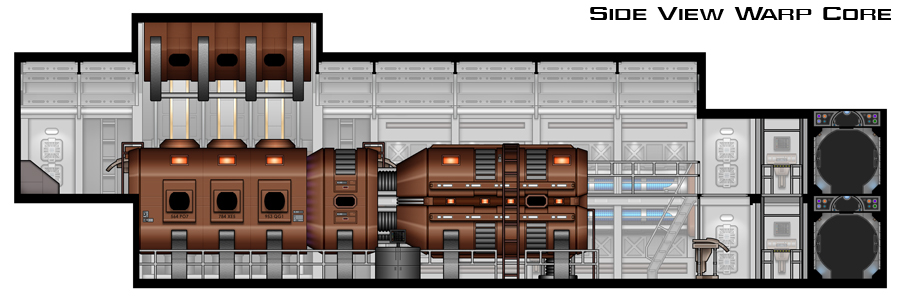
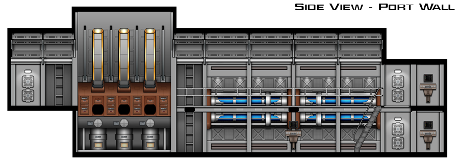
This is the side view of the warp core from the starboard side looking to port. Forward is to the right and aft is to the left. From this angle you can see the front of the core (or the injectors) connect into a larger reaction chamber located in the aft section of the engine room. Notice I have included a lift, additional work stations, and a large control console away from the core. I always thought it was silly to have Trip hanging off the front of the old core while it threatened to explode during a crisis. Can we say OSHA violation, boys and girls? But the most noticeable thing in this view is the cathedral over the reaction chamber. We have six plasma conduits (three on each side) that feed from the reaction chamber into buffers/modulators on the port and starboard walls of the chamber and then to a large transfer chamber above the core.
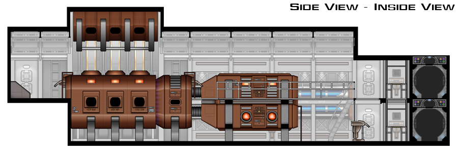
This is the same side view as before but with the closer deuterium injector removed. You can see how the gangway goes into the middle of the core and how the inside face of the deuterium injector looks. There is a small secondary control console and ladders attached to the reaction chamber that can be accessed by the gangway. I see dramatic shots of engineers running across the bridge to the control console during a crisis.
This is again the same view as before but with the warp core removed. You can see the entire side wall. I have included two alcoves on each side of the plasma cathedral for accessing all of the areas. The blue “tubes” that run along the wall are deuterium conditioners that chill and process the deuterium before it is fed into the injectors.
This is the aft section with the core removed.
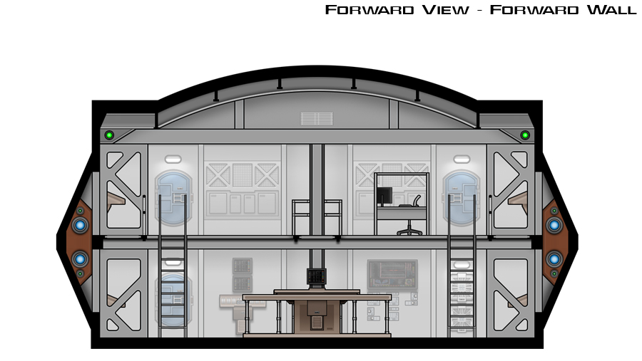
This is the forward section. From this angle you can get a good look at the main control console. I have placed the engineer’s work area to the right of the lift on the second level.
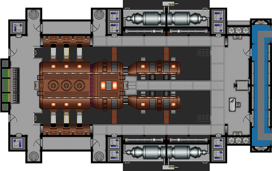
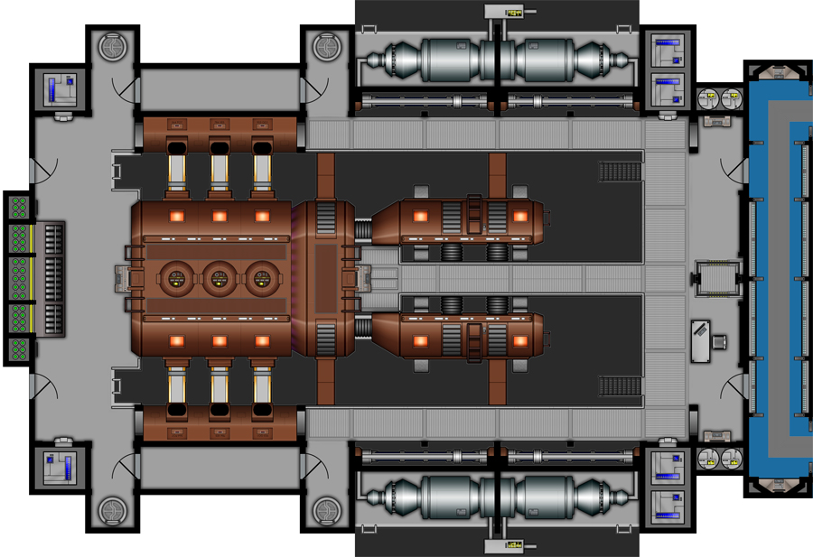
This is the floor plan for the first level. This should give you a better idea of how all of the details from the images above work together.
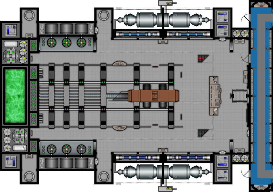
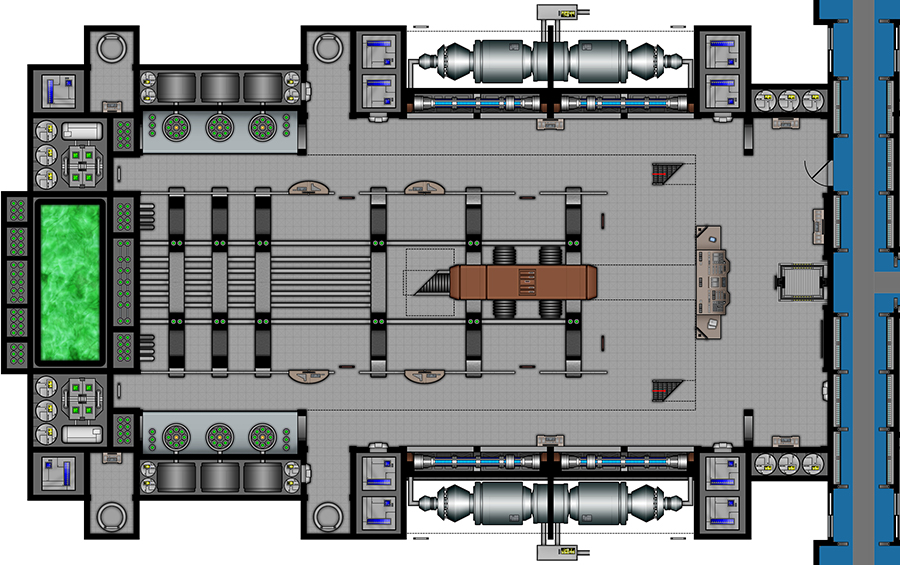
This is the floor plan for the second level. From this view you can see how the gangway runs between the injectors. You can also get a better idea of how all the gangways and access doors flow together.
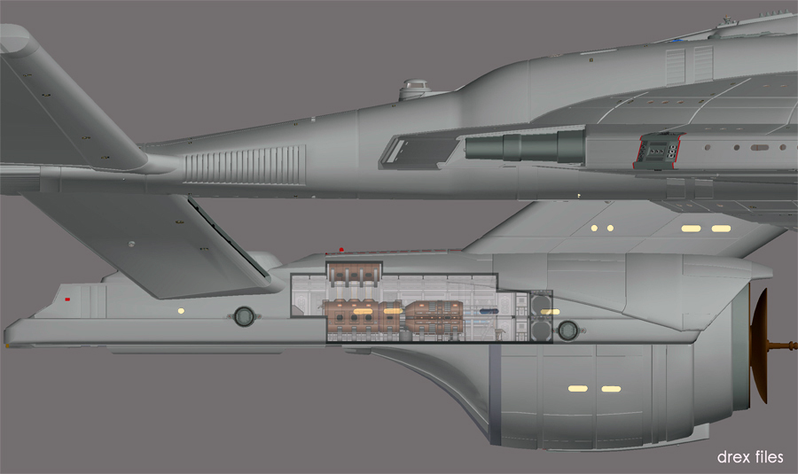
Finally, this is an overlay of the engine room over the refit hull to show its location. The CG model sports access doors on the dorsal side of the refit hull just above the engine room. These doors can be opened to easily access the experimental core for either hardware swap-outs or to install a completely different core in the future.
So what are your thoughts on the new refit engine room? Chew me up and spit me out. I need some feedback in a desperate way. I have working in a bubble to long for me to know if it is any good or not.
Please note: This is still a work in progress so nothing has been uploaded to the project website yet.
If anyone is new to The Enterprise Project feel free to go back through the older posts in this thread and get caught up. (That is why I resurrected it.) I would be happy to answer any and all questions, new and old! Visit The Enterprise Project to see all of it in full resolution.
For the 2010 Ships of the Line Calendar, Doug Drexler decided to refit his Enterprise NX-01 with a new secondary hull. To be honest I didn’t particularly like the additions when I first saw them and had no intention of EVER doing anything with it. But over the last four years I have grown to like the secondary hull. After a lot of requests I have relented and decided to create deck plans for it. (Actually I missed working on the project too.) I am here to show you kids the beginning stages of my work. You know what they say, never say never, and I should have kept my mouth shut.
To start this new series I began with the key piece of hardware for the new section: the warp core. When he introduced the refit on his blog Mr. Drexler had made it very clear that the new hull contained an experimental secondary warp core. This core would supplement the primary core still housed in the saucer but would represent the next evolutionary stage in warp technology. The purpose of the refit hull was to act as a “test bed” for Starfleet’s latest technology.
You would think designing a brand new core would be exciting and fun but it has been rather stressful. Nothing is more daunting than a blank piece of paper. After six months of designing, redesigning, screaming, scratching, paper fires, sobbing, hysterics, and panic attacks, I finally came up with an idea that I liked. I wanted to create something that looked similar but was different while bridging the gap between Enterprise and TOS. I was also driven to incorporate a better flow with some of the technology. The most pressing issue for me was to make this warp core BIGGER. I always felt the core we saw on the show was not big enough to generate the power the ship needed. Needless to say there were a lot of variables to keep a handle on… and to drive me insane.
But enough chatter… here is what I have.
To get us started (and to refresh everyone’s memory) this is a copy of the plan that Doug Drexler put together to build the refit computer model.
This is the new warp core. This view is from the forward section of the engine room looking aft at the front of the core. The core is about fifteen feet tall and twice the width of the original engine. If you look closely you will see that there is an upper level “walkway” that runs through the middle of the core. (The floor plan will describe this better.) The two “lobes” on each side are the deuterium injectors while the rectangular “box” under the gantry is the antimatter injector. The front of the antimatter injector pops open and slides out to allow access to the injectors themselves.
This is the same view but with the forward ceiling removed to reveal the aft cathedral. This area houses the plasma conduits that feed into the warp nacelles. Notice how it looks very similar to a certain set from TOS?
This is the side view of the warp core from the starboard side looking to port. Forward is to the right and aft is to the left. From this angle you can see the front of the core (or the injectors) connect into a larger reaction chamber located in the aft section of the engine room. Notice I have included a lift, additional work stations, and a large control console away from the core. I always thought it was silly to have Trip hanging off the front of the old core while it threatened to explode during a crisis. Can we say OSHA violation, boys and girls? But the most noticeable thing in this view is the cathedral over the reaction chamber. We have six plasma conduits (three on each side) that feed from the reaction chamber into buffers/modulators on the port and starboard walls of the chamber and then to a large transfer chamber above the core.
This is the same side view as before but with the closer deuterium injector removed. You can see how the gangway goes into the middle of the core and how the inside face of the deuterium injector looks. There is a small secondary control console and ladders attached to the reaction chamber that can be accessed by the gangway. I see dramatic shots of engineers running across the bridge to the control console during a crisis.
This is again the same view as before but with the warp core removed. You can see the entire side wall. I have included two alcoves on each side of the plasma cathedral for accessing all of the areas. The blue “tubes” that run along the wall are deuterium conditioners that chill and process the deuterium before it is fed into the injectors.
This is the aft section with the core removed.
This is the forward section. From this angle you can get a good look at the main control console. I have placed the engineer’s work area to the right of the lift on the second level.
This is the floor plan for the first level. This should give you a better idea of how all of the details from the images above work together.
This is the floor plan for the second level. From this view you can see how the gangway runs between the injectors. You can also get a better idea of how all the gangways and access doors flow together.
Finally, this is an overlay of the engine room over the refit hull to show its location. The CG model sports access doors on the dorsal side of the refit hull just above the engine room. These doors can be opened to easily access the experimental core for either hardware swap-outs or to install a completely different core in the future.
So what are your thoughts on the new refit engine room? Chew me up and spit me out. I need some feedback in a desperate way. I have working in a bubble to long for me to know if it is any good or not.
Please note: This is still a work in progress so nothing has been uploaded to the project website yet.
If anyone is new to The Enterprise Project feel free to go back through the older posts in this thread and get caught up. (That is why I resurrected it.) I would be happy to answer any and all questions, new and old! Visit The Enterprise Project to see all of it in full resolution.
")

 And with new plans!