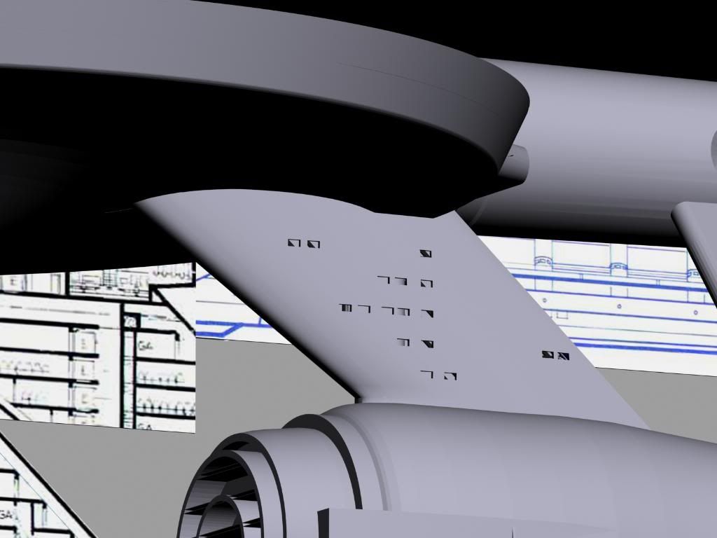
Well, vacation ends today; but, work continues:
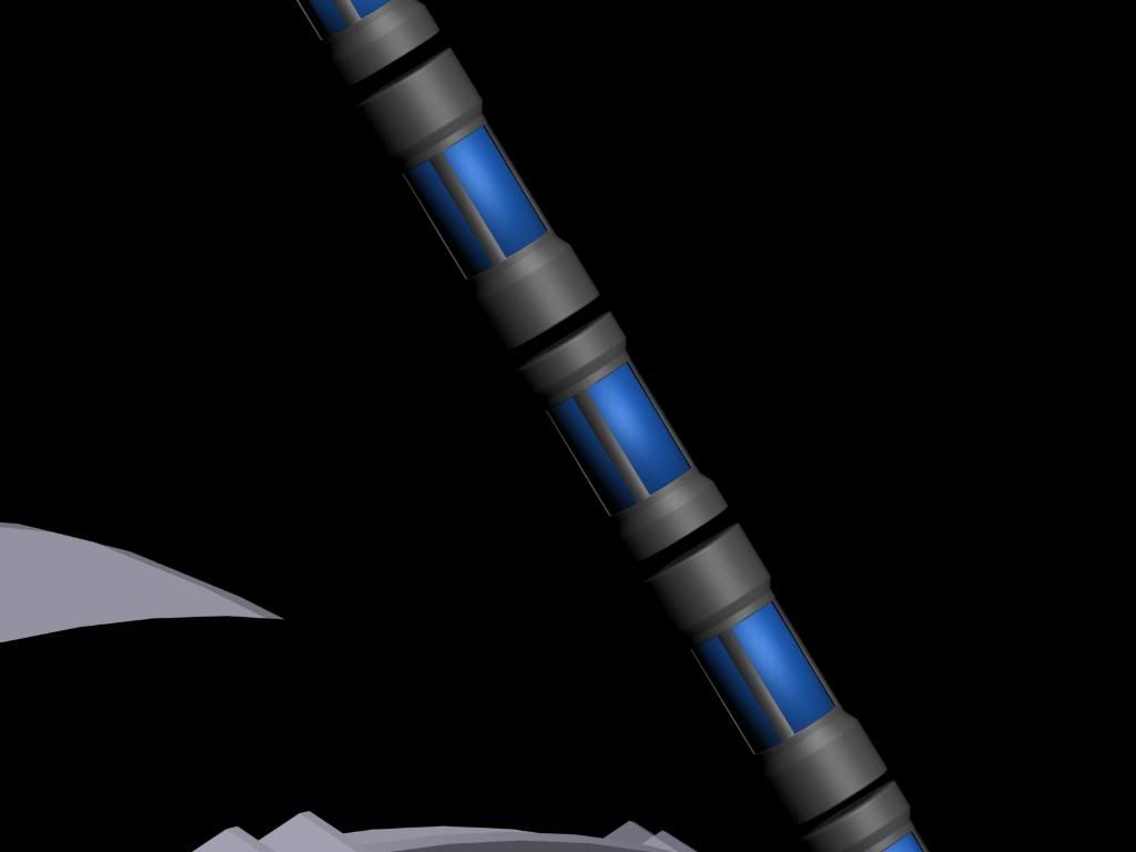
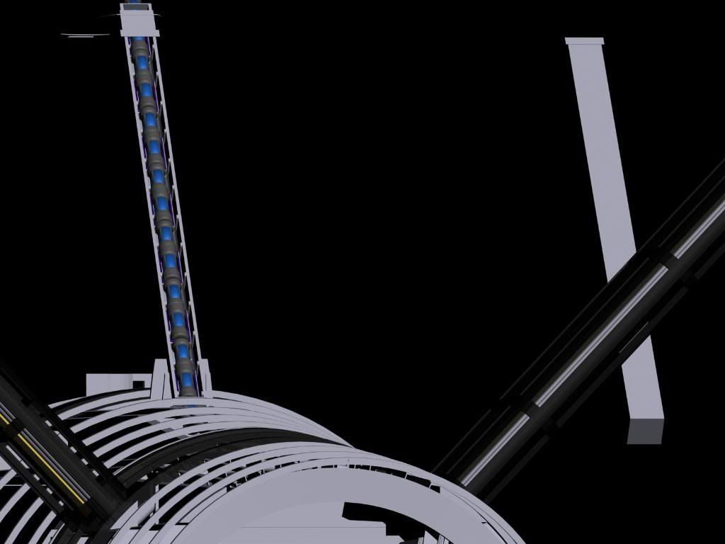
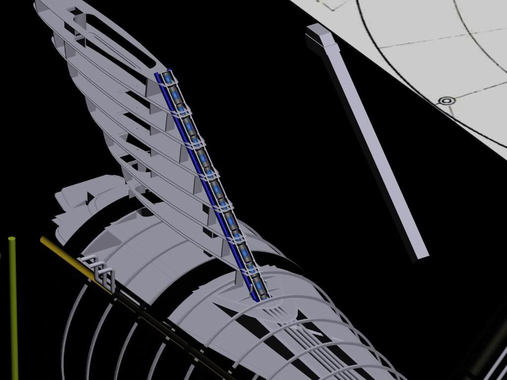
This is my rendition of the "core". This is the primary reaction chamber feeding into
main engineering..
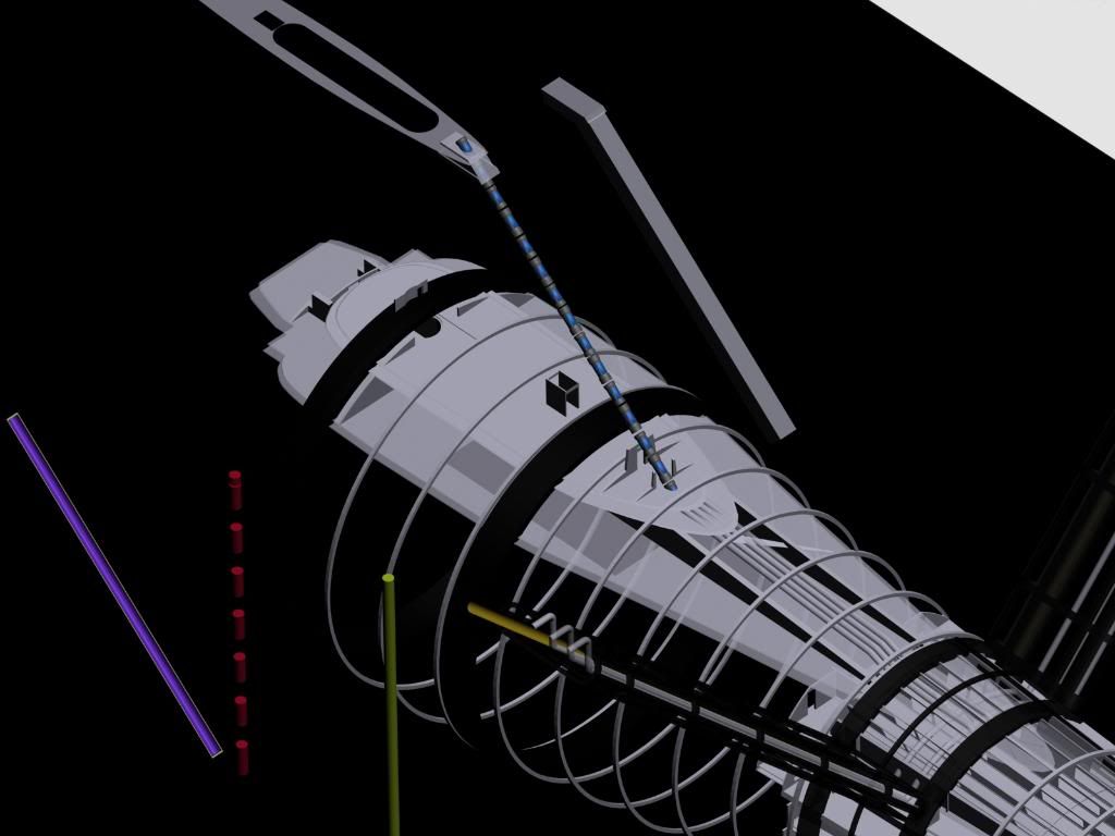
..and this is what it's looking like in place at the moment.
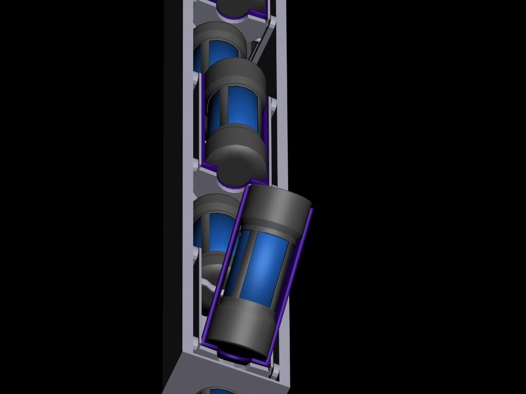
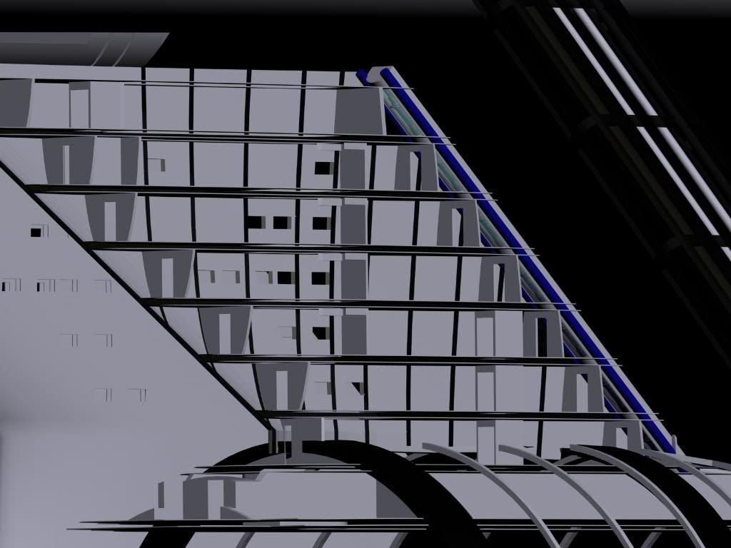
It consists of large and small segments at the moment. The smaller segments will
wind up being anchor points connecting the larger portions to the dorsal spine.
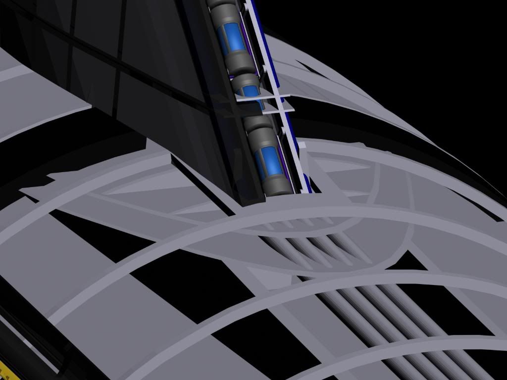
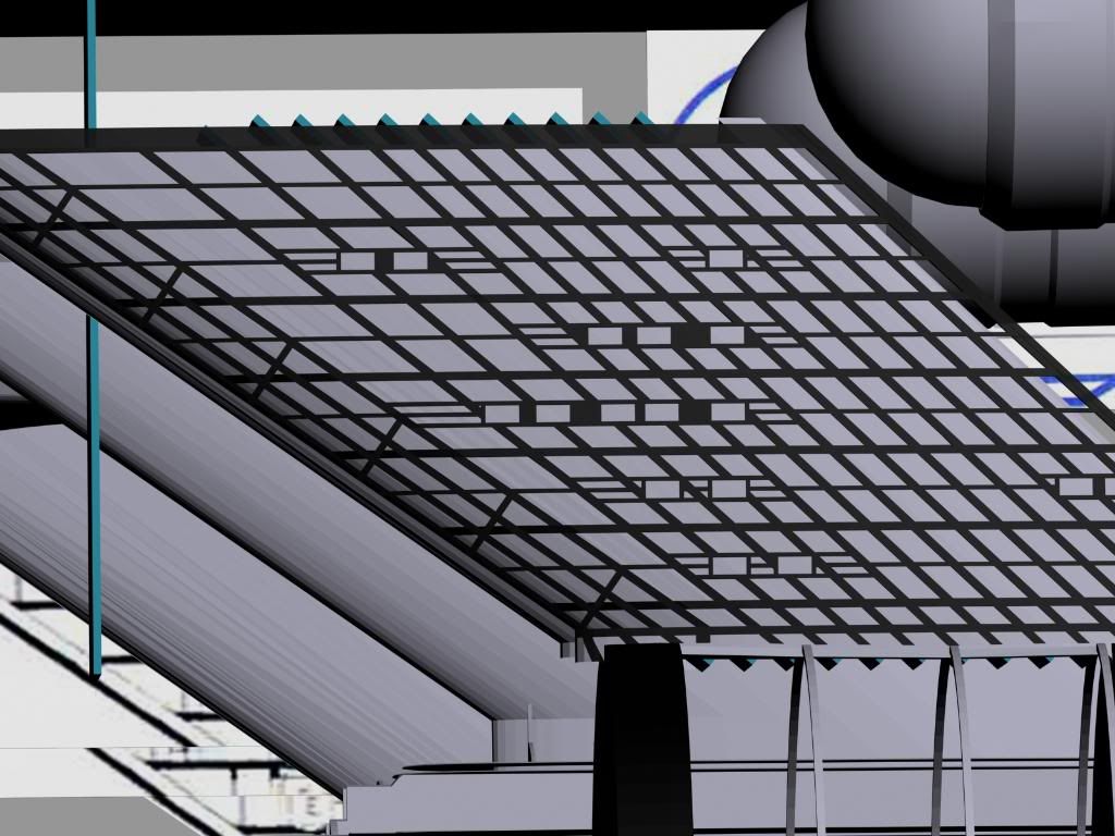
The half-round purple and gold section in view will end up being the seat these
sections rest in. I've got a ways to go in finishing the core out, obviously.
The next step is to design the connections and ejection seats.
This is my rendition of the "core". This is the primary reaction chamber feeding into
main engineering..
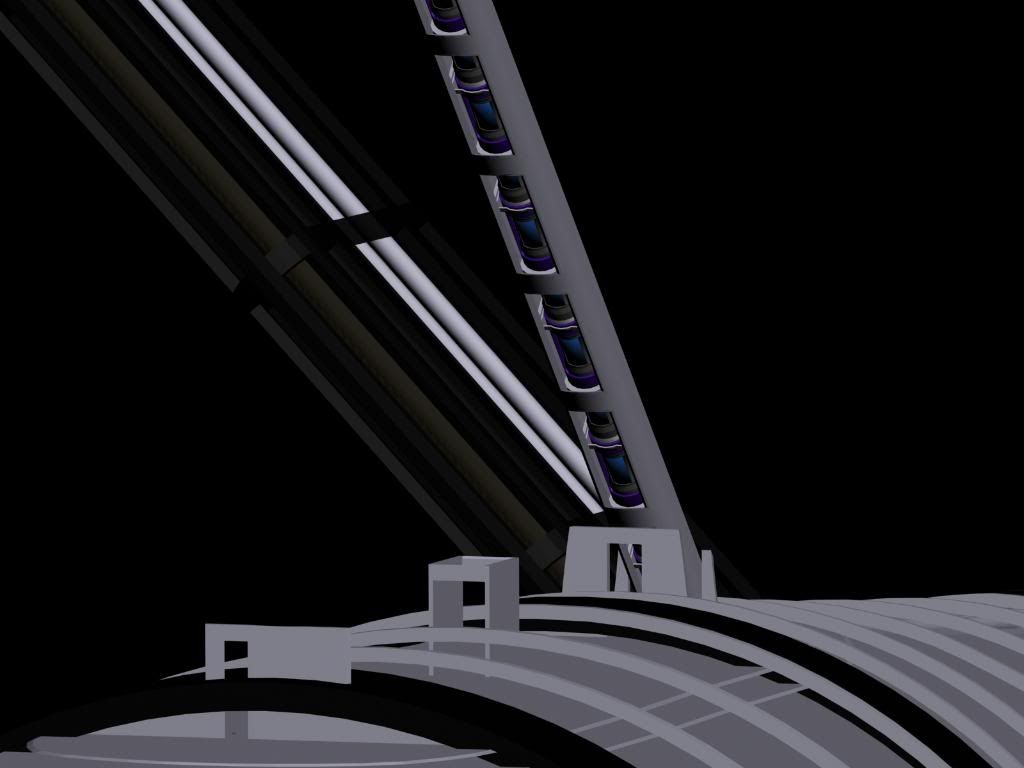
..and this is what it's looking like in place at the moment.
It consists of large and small segments at the moment. The smaller segments will
wind up being anchor points connecting the larger portions to the dorsal spine.
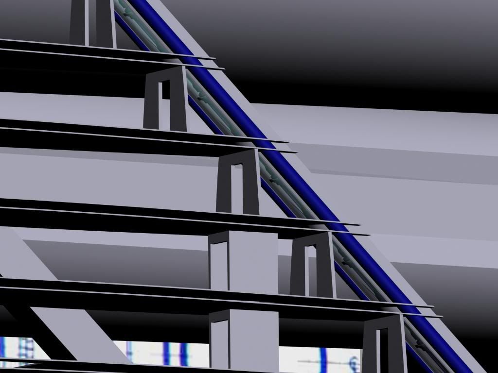
The half-round purple and gold section in view will end up being the seat these
sections rest in. I've got a ways to go in finishing the core out, obviously.
The next step is to design the connections and ejection seats.
")