-
Welcome! The TrekBBS is the number one place to chat about Star Trek with like-minded fans.
If you are not already a member then please register an account and join in the discussion!
You are using an out of date browser. It may not display this or other websites correctly.
You should upgrade or use an alternative browser.
You should upgrade or use an alternative browser.
My TOS Shuttlecraft...
- Thread starter Warped9
- Start date
I should have put off posting these a day or so ago because just yesterday evening I've already got the interior lines of the exterior hull added in as well as the hatchway between hulls passage. Of interesting note of how things have seemed to magically line up: the port side service panel see under the stabilizer just happens to line up near perfectly with my waste management system (the toilet) and the service panel on the starboard side lines up just right with what I designated the ship's electrical system. Neato.Warped9 said:
Slow but steady progress.
Great work there :thumbsup:
This was raised on another site:
I was also able to include something I glimsped in TG7 episode. When McCoy and Yeoman Mears are jettisoning equipment one of the things they dispose of is a larger cylindrical object from the aft cabin which is never identified. My notion is that they had dismantled the aft port inside bulkead and subsequently jettisoned the onboard WMS and its sump tank, the food & beverage processor and the adjecent cylindrical shaped raw matter/filter tank for the f/b processor. That cylindrical object has already been added to my updated (yet to be posted) deck plan and can be seen between the inner and outer hulls connected to the f/b processor. The WMS has a pipe connection to the port service access panel (under the stabilizer) for routine flushing when necessary. Alongside that the raw matter tank also has a pipe connection to the port service access panel for periodic flushing and replensihment for the f/b processor. Incidentally the crew's actions support my notion of futuristic lightweight material because they're dumping all this equipment and it's still not meeting Scotty's requirement of losing 500 pounds. Hmm.
On the starboard side the service access panel provides access to the ship's electrical system (something like an RV's or camp trailer's external electrical outlet) for powering any extravehicular equipment. Between the hulls on the starboard side is the ship's central electrical system, from whithin the ship Scotty accessed the ship's batteries.
Although I hadn't planned for it the craft's interior could possibly allow for a small temporary airlock setup. The space between the hulls is too small, but an airlock setup could be erected after removing the port side aft seats. This occasionally could be usefull for a mission requiring extravehicular activity in space. Or the crew could just as easily bring along EVA suits and depressurize the entire cabin.
I'm also looking at including storage bunkers overhead on each side to hold EVA gear as there may well be enough space between the hulls.
On another note I'm still considering how best to share the finished plans with folks. Although I admittedly could use the money I've leaning not to make them available for sale in hardcopy or electronic. Instead I'll make them freely available in downloadable pdf file form. It could be in two sizes: one size for easy printing on 8x11 paper for home printers and a larger original 11x17. Most folks would likely have to transfer the larger size file to a USB drive or CD and have them printed at pretty well any local copying shop to have their own fullsize hardopy plans. Doing this kind of work as related to Star Trek is a hobby and labour of love for me and I don't see myself driven for monetary gain for it. I enjoy sharing it with other like minded folks.
Welllll... The "waste management system" happens be next to the shuttlecraft's own onboard food/beverage processor, which for all intents and purposes is a nanotech engine device (and to hell with TNG's nanites episode which was waaay behind the curve in introducing that idea as something "new" in the Trek universe). No doubt some of the crew's "waste" or even just plain garbage can be "reprocessed" into usable matter such as, ahem, drinking water if necessary. With such technology at hand it's likely the Galileo's group wouldn't have died of thirst or starvation anytime soon if they could avoid being killed by Tarsus II's native inhabitants.by portland182
Recycled as what?
I'm hoping that it's not as bad as I imagine...
Jim
I was also able to include something I glimsped in TG7 episode. When McCoy and Yeoman Mears are jettisoning equipment one of the things they dispose of is a larger cylindrical object from the aft cabin which is never identified. My notion is that they had dismantled the aft port inside bulkead and subsequently jettisoned the onboard WMS and its sump tank, the food & beverage processor and the adjecent cylindrical shaped raw matter/filter tank for the f/b processor. That cylindrical object has already been added to my updated (yet to be posted) deck plan and can be seen between the inner and outer hulls connected to the f/b processor. The WMS has a pipe connection to the port service access panel (under the stabilizer) for routine flushing when necessary. Alongside that the raw matter tank also has a pipe connection to the port service access panel for periodic flushing and replensihment for the f/b processor. Incidentally the crew's actions support my notion of futuristic lightweight material because they're dumping all this equipment and it's still not meeting Scotty's requirement of losing 500 pounds. Hmm.
On the starboard side the service access panel provides access to the ship's electrical system (something like an RV's or camp trailer's external electrical outlet) for powering any extravehicular equipment. Between the hulls on the starboard side is the ship's central electrical system, from whithin the ship Scotty accessed the ship's batteries.
Although I hadn't planned for it the craft's interior could possibly allow for a small temporary airlock setup. The space between the hulls is too small, but an airlock setup could be erected after removing the port side aft seats. This occasionally could be usefull for a mission requiring extravehicular activity in space. Or the crew could just as easily bring along EVA suits and depressurize the entire cabin.
I'm also looking at including storage bunkers overhead on each side to hold EVA gear as there may well be enough space between the hulls.
On another note I'm still considering how best to share the finished plans with folks. Although I admittedly could use the money I've leaning not to make them available for sale in hardcopy or electronic. Instead I'll make them freely available in downloadable pdf file form. It could be in two sizes: one size for easy printing on 8x11 paper for home printers and a larger original 11x17. Most folks would likely have to transfer the larger size file to a USB drive or CD and have them printed at pretty well any local copying shop to have their own fullsize hardopy plans. Doing this kind of work as related to Star Trek is a hobby and labour of love for me and I don't see myself driven for monetary gain for it. I enjoy sharing it with other like minded folks.
I'm definitely diggin' this...
The one thing that bugs me more than anything else in "fan-trek" design is the tendency to make all walls "single pencil-line" thickness. I've always wanted the walls on the TOS Enterprise to be the same thickness as what we saw in "Charlie X" for the brig... easily 2' thick. That lets them have structure inside, plumbing, whatever.
The AMT Galileo model just pissed me off for the same reason. We KNEW that the floor had a hatch in it that Scotty could reach down inside of... but the model had a single sheet of plastic there. So unless that hatch was a TARDIS hatch...
What you've done here so far is the first time I've seen the TOS shuttle done in a way that actually makes sense to me. Keep it up!
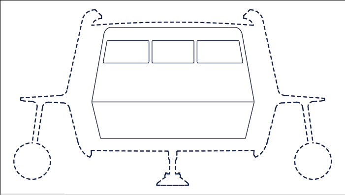
By the way... one suggestion. We know that the Enterprise had a landing-strip-type shuttlebay, but this was a wide-usage shuttle design, right? Well... look at the top of the shuttle, where the outside walls sort of "roll in" toward the centerline. What do you think those are for?
To me, I see that as the receiving end for a "rail-type" docking crane. I'd assume that some ships still use the originally-conceived MJ concept that they eventually used in the NX-01 design. That's a perfect location for the docking crane to latch onto, don't you think?
The one thing that bugs me more than anything else in "fan-trek" design is the tendency to make all walls "single pencil-line" thickness. I've always wanted the walls on the TOS Enterprise to be the same thickness as what we saw in "Charlie X" for the brig... easily 2' thick. That lets them have structure inside, plumbing, whatever.
The AMT Galileo model just pissed me off for the same reason. We KNEW that the floor had a hatch in it that Scotty could reach down inside of... but the model had a single sheet of plastic there. So unless that hatch was a TARDIS hatch...
What you've done here so far is the first time I've seen the TOS shuttle done in a way that actually makes sense to me. Keep it up!
By the way... one suggestion. We know that the Enterprise had a landing-strip-type shuttlebay, but this was a wide-usage shuttle design, right? Well... look at the top of the shuttle, where the outside walls sort of "roll in" toward the centerline. What do you think those are for?
To me, I see that as the receiving end for a "rail-type" docking crane. I'd assume that some ships still use the originally-conceived MJ concept that they eventually used in the NX-01 design. That's a perfect location for the docking crane to latch onto, don't you think?
Well, if you make it available for free, I'll take it that way... but the quality of your work is far superior to some ... well, some crap I've paid for in the past... so if you want to charge a nominal fee to provide a slip-covered printed version (perhaps with the "original artist signature" in the title block area?) I'd say that you could charge $15.00 a pop for these, no more, and it'd be considered "fair compensation" for the reproduction without necessarily bringing the wrath of Paramount down on you!Warped9 said:On another note I'm still considering how best to share the finished plans with folks. Although I admittedly could use the money I've leaning not to make them available for sale in hardcopy or electronic. Instead I'll make them freely available in downloadable pdf file form. It could be in two sizes: one size for easy printing on 8x11 paper for home printers and a larger original 11x17. Most folks would likely have to transfer the larger size file to a USB drive or CD and have them printed at pretty well any local copying shop to have their own fullsize hardopy plans. Doing this kind of work as related to Star Trek is a hobby and labour of love for me and I don't see myself driven for monetary gain for it. I enjoy sharing it with other like minded folks.
I'd love to add a set of high-resolution heavy-paper folded prints, in their own slipcover envelope, to my collection of blueprints.
Hey, I do all my professional design work on the computer but I still print everything out on paper... it's just easier to look at and GRASP it that way.
So my input... make it official and actually PUBLISH 'em.
I use different line thickness for different things on my drawings. For instance I use a very thin .25 pt. line not touching anything at either end to denote the centerline of a curved surface. It's rather apparent on a computer monitor, but it's a very fine thing on hardcopy as it should be. My exterior outlines are 2 pt. and the remaining lines vary from .5 to 1 pt. in thickness depending on what I'm trying to show.Cary L. Brown said:
I'm definitely diggin' this...
The one thing that bugs me more than anything else in "fan-trek" design is the tendency to make all walls "single pencil-line" thickness. I've always wanted the walls on the TOS Enterprise to be the same thickness as what we saw in "Charlie X" for the brig... easily 2' thick. That lets them have structure inside, plumbing, whatever.
I admit that I'm going to a lot of trouble to make the shuttlecraft more "real" or at least credible, but then again I'm trying to build on things that were suggested or inferred in TOS itself. I'm also trying to apply real world and/or at least respectable science fiction ideas to the project.
In regards to how the craft are "manhandled" in the hangar deck. Well, they do have the means to manipulate antigravity and so some sort of such device could be used to move the craft around. It doesn't have to be an actual crane lowered from the ceiling although something like that could possibly be done. I haven't thought much about this part yet, but I'm sure it will come up when I likely tackle drawing/planning out the hangar deck and lower shuttlecraft maintenance facility area.
Ironically though, those fanboy drawings are probably closer to future reality than two-foot-thick walls are. I find it hard to imagine that three centuries of advances in metallurgy and nanotechnology will still result in walls that have to be two feet thick for structural purposes. Of course, paper-thin walls look odd to our primitive early twenty-first century eyes, so there you go.Cary L. Brown said:
The one thing that bugs me more than anything else in "fan-trek" design is the tendency to make all walls "single pencil-line" thickness. I've always wanted the walls on the TOS Enterprise to be the same thickness as what we saw in "Charlie X" for the brig... easily 2' thick. That lets them have structure inside, plumbing, whatever.
Your shuttle is looking very sleek, Warped9! I really appreciate the thought you're putting into this project. :thumbsup:
Well, I doubt that for a multitude of reasons. First off, no matter what "tweaks" we come up with, the basic forces that hold matter together are not subject to our "reinvention" these days. You have strong nuclear force, weak nuclear force, covalent bond force, and ionic charge force.Professor Moriarty said:Ironically though, those fanboy drawings are probably closer to future reality than two-foot-thick walls are. I find it hard to imagine that three centuries of advances in metallurgy and nanotechnology will still result in walls that have to be two feet thick for structural purposes. Of course, paper-thin walls look odd to our primitive early twenty-first century eyes, so there you go.
This means that, short of totally reinventing the concept of matter at the well-below-subatomic-level, we are fundamentally limited to just how strong you can ever make a material. It's not just a matter of different heat-treat operations or minor variations in alloying. We've got that stuff pretty well figured out these days.
Star Trek addressed this idea, eventually, by cheating... instead of redefining matter, they created a "pseudo-structure" called the "structural integrity force field." I can live with this.
Now, let's assume that even though there are laws-of-physics limitations on matter, we can still get a fair amount of additional material strength out by further "tweaking" things. Even with that, you STILL get a much stronger structure by virtue of reducing aspect ratio than you do by having a "long skinny section." This is why you see large open-structure trusses used in lightweight, strong construction. This is also why you'd use a thicker hollow-lattice-structure wall instead of a thinner, solid-material wall... you can get better strength for less mass penalty by going that way. And you also get the advantage of having the spaces IN the latticework that can be used for non-habitable space needs... water, gas, plumbing/wiring/etc, small support systems...
No matter how much we ever manage to improve matter, the basic geometry-based rules of engineering will not change. Trust me... thin solid walls aren't even used in the construction of your house... you have a crude 2x4 lattice with a thin skin of sheetrock over it, after all.
The trick in designing any vessel, space-borne or otherwise, is to figure out the best tradeoff between mass, volume, and habitable space (which is not the same as volume after all!) By making the floor/ceiling thickness and the wall thickness greater, you can increase overall strength as a ratio to the mass of the vessel, and gain space for hardware that doesn't need to be placed it ROOMS at all. If you go with paper-thin walls... where do you put the equipment? It has to be placed in compartments which are then no longer available for human habitation, right? You need more overall structure as well, to get the same strength as the more distributed structure gives you, and you pay a mass penalty for that as well.
Just remember... the best mechanical structures we have today are based upon HONEYCOMB structures - a relatively small amount of total mass but very uniformly distributed and with no elements under anything but tensile loading until the whole part starts to buckle.
One of the things I'm very interested in trying my hand at when I'm finished all my views is rendering the ship's structural spaceframe as I call it. This will be the basic skeletal framework that the inner and outer hulls are fastened to. I have a reasonably clear picture of it in my head so the trick will be for me to get it right on paper. My cutaway views are showing only parts of that spaceframe, but I think it would be interesting to see the assembly on its own and bare of any fittings.
Think it's worth doing?")
Think it's worth doing?
Well, you already know what >I< am going to say... HELL YES!Warped9 said:
One of the things I'm very interested in trying my hand at when I'm finished all my views is rendering the ship's structural spaceframe as I call it. This will be the basic skeletal framework that the inner and outer hulls are fastened to. I have a reasonably clear picture of it in my head so the trick will be for me to get it right on paper. My cutaway views are showing only parts of that spaceframe, but I think it would be interesting to see the assembly on its own and bare of any fittings.
Think it's worth doing?
Whether or not anyone else agrees is a whole 'nother topic.
Another point... one of the more challenging things for you, IMHO, is how you're going to draw the door panels in a way that looks "right" to the typical viewer.
Here's my take. The door is actually a sandwich structure. There's an interior panel, and an exterior panel, and in between there's what's effectively a gas bladder (or possibily pneumatic cylinders, but a bladder is actually better in this case, IMHO).
So, you deflate the "air bag" and the inner and outer door panel sections draw in towards each other, to a hard-stop situation... the inner doorpanel "wall" moves outwards and the outer one moves inwards. This breaks the seals on both sides, and also allows the "deflated" door panel to be retracted into a pocket in the wall.
The nice thing about a gas bladder is that in a vacuum, it functions without the need for any expended power whatsoever. It relies only on the laws of physics.
Of course, you might want redundant systems. That is, a linear-drive motor at all four corners of the panel as well, in case the bladder (which would of course be self-healing) got seriously perforated... but the bladder would be there in case the motors failed or the gears stripped or whatever. You'd probably also have some sort of "locking" mechanism in there to further secure it.. in which case, you'd need a manual "unlocking" feature in case the power to that hatch failed completely... otherwise, you'd be permanently stuck inside (unless you wanted to burn out through the hull with a phaser???)
In any case... while detailing the wall structure is a "luxury," detailing the door system is something that I'd say is almost a necessity. But it ought to be fun... especially since you're sort of playing "engineer in training" here!
Suffice to say that I seriously doubt I'll ever apply this level of effort again to any other Trek project. Can you imagine trying to do this sort of thing with the E herself?  And, of course, there's a level of detail I'm not getting into such as wiring details and what all the controls and instrumentation actually do. The SCL will involve a lot of work collectively, but I seriously doubt any one subject will require the measure of detail I'm putting into this shuttlecraft project. Initially I wasn't keen on doing the ceiling plan and multiple cutaway view or the variant internal arrangements, but I'll be doing those.
From my disclaimer: "This set of general plans is not meant as exhaustive and is intended primarily for familiarization reference only. It is primarily intended for Acadeny cadets, interested applicants and enthusiasts within the general public."
And, of course, there's a level of detail I'm not getting into such as wiring details and what all the controls and instrumentation actually do. The SCL will involve a lot of work collectively, but I seriously doubt any one subject will require the measure of detail I'm putting into this shuttlecraft project. Initially I wasn't keen on doing the ceiling plan and multiple cutaway view or the variant internal arrangements, but I'll be doing those.From my disclaimer: "This set of general plans is not meant as exhaustive and is intended primarily for familiarization reference only. It is primarily intended for Acadeny cadets, interested applicants and enthusiasts within the general public."
This project has just been expanded. I started out with an ambitious enough goal: to reconcile the inconsistencies between the full-size exterior and interior mockups of the shuttlecraft shown onscreen and create a credible integrated whole vehicle that still looked near exactly like what we saw onscreen. If I may say so I think for the most part I’ve been successful so far. The interior of my shuttlecraft is really only modestly smaller in overall length and height than the full-size interior onscreen and the exterior of my ship is only about 15-20% bigger than the onscreen full-size mockup. Yes, it’s a compromise, but to have stayed totally true to either the onscreen exterior mockup or interior set would have created huge problems. An exterior consistent with the full-size interior set would have resulted in a ship about 31ft. or so long and just too big to be handled practically within the hangar deck of a 947Ft. starship, and maybe a 1080ft. starship as well. And staying true to the exterior mock-up would have resulted in a ship with an interior far too cramped to be consistent with the events and actions we saw depicted within the craft onscreen.
Now in regards to the expansion of this project. I started out initially simply to render the exterior views as well as a few chosen cross sections. Problem is that as I progressed I discovered that other elements seemed to be begging me to elaborate upon them. And even as I tried to resist the impulse (and consequent extra work) I find myself unable to ignore the urge. I can only accept that this is the obsessive/perfectionist aspect of my character coming into play. So the completion of this project is going to take a little longer.
And so here is my current project outline and status:
Sheet 0 – Cover Page
Sheet 1 – Class F Port Elevation (completed)
Sheet 2 – Class F Starboard Elevation (completed)
Sheet 3 – Class F Bow Elevation (completed)
Sheet 4 – Class F Aft Elevation (completed)
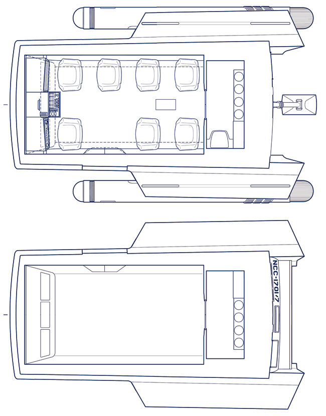
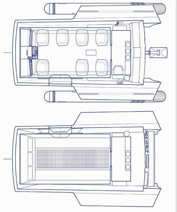
Sheet 5 – Class F Top Plan (completed)
Sheet 6 – Class F Bottom Plan (completed)
Sheet 7 – Class F Port Cutaway (completed)
Sheet 8 – Class F Starboard Cutaway (completed)
Sheet 9 – Class F Main Cabin Bow Cutaway
Sheet 10 – Class F Main Cabin Aft Cutaway
Sheet 11 – Class F Aft Cabin Aft Cutaway
Sheet 12 – Class F Deck Plan (near completion)
Sheet 13 – Class F Ceiling Plan (near completion)
Sheet 14 – Class F Inner Hull: port, bow and top
Sheet 15 – Class F Inner Hull: starboard, aft and bottom
Sheet 16 – Class F Structural Spaceframe: port, bow and top
Sheet 17 – Class F Structural Spaceframe: starboard, aft and bottom.
Sheet 18 – Class F Shuttlecraft History (completed)
Sheet 19 – Class F Medical Support Variant Interior Configuration
Sheet 20 – Class F Extended Survey Variant Interior Configuration
Sheet 21 – Class H Exterior: port, bow and top (completed)
Sheet 22 – Class H Exterior: starboard, aft and bottom (completed)
Sheet 23 – Class H Interior: port, bow and deck
Sheet 24 – Class H Interior: starboard, aft and ceiling
Sheet 25 – U.S.S. Enterprise Shuttlecraft Complement (completed)
Sheet 26 – Afterward and Notes.
Sheet 27 – “Forced Landing” (the Galileo plummets towards the surface of Taurus II)
Sheet 28 – “The Hangar Deck” (a group of shuttlecraft within the Enterprise hangar)
Sheet 29 – “Beta Lyra” 1 (the shuttlecraft Copernicus passes near Beta Lyra)
Sheet 30 – “Sightseeing” (the interior of Copernicus as it approaches Beta Lyra)
Sheet 31 – “On-Site Survey” (Copernicus and its crew on the surface of an icy planetoid)
Sheet 32 – “Planetfall” (the shuttle crew fans out after landing)
A few remarks regarding the above outline. Sheets 14 and 15 will lay out the ship’s inner hull. While drawing the deck and ceiling plans I couldn’t help but notice that there were some aspects I would be challenged to detail and show properly. And so I decided to render the inner hull exterior shell as a separate element with all the adjacent components attached. Essentially my reasoning is that the inner hull component is relegated mostly to sustaining the crew while the exterior shell is devoted primarily to the craft’s mobility (propulsion and antigrav capability) and survivability (shielding). Attached to the inner hull shell will be the life support systems such as the waste management, food and beverage processor and environmental control systems. Also shown will be much of the ship’s control systems linkages.
Sheets 27-32 may be flexible. A number of those images have already been posted on my Never seen TOS scenes thread, but I want to do them again from scratch and preferably in larger size. I may also add or substitute one or two of them with something else.
In extent from this project my mind is spinning with other shuttlecraft related ideas. Of course there’s the Enterprise’s hangar deck and shuttlecraft maintenance facility situated below. There’s also my adaptations of the TAS shuttles. And finally there’s another shuttlecraft variation of my own design that I initially did way back in the mid ‘70s. In concept it’s my take on a TOS era runabout. It’s essentially the Class F body stretched out some with somewhat Enterprise like warp nacelles slung aftwards and below. My intent was a more credible live-action version of the TAS scoutship seen in “The Slaver Weapon.” Still, this vehicle would be too large to be part of the regular complement of shuttlecraft housed aboard ship.
And finally there are the shuttlecraft from TMP (of which there are at least two versions to my knowledge) and TFF. Suffice to say that none of the other shuttles are likely to get the same measure of attention to detail that I’m devoting to the Class F. I’ll be content to leave that to someone else… Mind you no one knows anything of the interior layout of the TMP shuttlecraft. Hmm… (-:
Now in regards to the expansion of this project. I started out initially simply to render the exterior views as well as a few chosen cross sections. Problem is that as I progressed I discovered that other elements seemed to be begging me to elaborate upon them. And even as I tried to resist the impulse (and consequent extra work) I find myself unable to ignore the urge. I can only accept that this is the obsessive/perfectionist aspect of my character coming into play. So the completion of this project is going to take a little longer.
And so here is my current project outline and status:
Sheet 0 – Cover Page
Sheet 1 – Class F Port Elevation (completed)
Sheet 2 – Class F Starboard Elevation (completed)
Sheet 3 – Class F Bow Elevation (completed)
Sheet 4 – Class F Aft Elevation (completed)
Sheet 5 – Class F Top Plan (completed)
Sheet 6 – Class F Bottom Plan (completed)
Sheet 7 – Class F Port Cutaway (completed)
Sheet 8 – Class F Starboard Cutaway (completed)
Sheet 9 – Class F Main Cabin Bow Cutaway
Sheet 10 – Class F Main Cabin Aft Cutaway
Sheet 11 – Class F Aft Cabin Aft Cutaway
Sheet 12 – Class F Deck Plan (near completion)
Sheet 13 – Class F Ceiling Plan (near completion)
Sheet 14 – Class F Inner Hull: port, bow and top
Sheet 15 – Class F Inner Hull: starboard, aft and bottom
Sheet 16 – Class F Structural Spaceframe: port, bow and top
Sheet 17 – Class F Structural Spaceframe: starboard, aft and bottom.
Sheet 18 – Class F Shuttlecraft History (completed)
Sheet 19 – Class F Medical Support Variant Interior Configuration
Sheet 20 – Class F Extended Survey Variant Interior Configuration
Sheet 21 – Class H Exterior: port, bow and top (completed)
Sheet 22 – Class H Exterior: starboard, aft and bottom (completed)
Sheet 23 – Class H Interior: port, bow and deck
Sheet 24 – Class H Interior: starboard, aft and ceiling
Sheet 25 – U.S.S. Enterprise Shuttlecraft Complement (completed)
Sheet 26 – Afterward and Notes.
Sheet 27 – “Forced Landing” (the Galileo plummets towards the surface of Taurus II)
Sheet 28 – “The Hangar Deck” (a group of shuttlecraft within the Enterprise hangar)
Sheet 29 – “Beta Lyra” 1 (the shuttlecraft Copernicus passes near Beta Lyra)
Sheet 30 – “Sightseeing” (the interior of Copernicus as it approaches Beta Lyra)
Sheet 31 – “On-Site Survey” (Copernicus and its crew on the surface of an icy planetoid)
Sheet 32 – “Planetfall” (the shuttle crew fans out after landing)
A few remarks regarding the above outline. Sheets 14 and 15 will lay out the ship’s inner hull. While drawing the deck and ceiling plans I couldn’t help but notice that there were some aspects I would be challenged to detail and show properly. And so I decided to render the inner hull exterior shell as a separate element with all the adjacent components attached. Essentially my reasoning is that the inner hull component is relegated mostly to sustaining the crew while the exterior shell is devoted primarily to the craft’s mobility (propulsion and antigrav capability) and survivability (shielding). Attached to the inner hull shell will be the life support systems such as the waste management, food and beverage processor and environmental control systems. Also shown will be much of the ship’s control systems linkages.
Sheets 27-32 may be flexible. A number of those images have already been posted on my Never seen TOS scenes thread, but I want to do them again from scratch and preferably in larger size. I may also add or substitute one or two of them with something else.
In extent from this project my mind is spinning with other shuttlecraft related ideas. Of course there’s the Enterprise’s hangar deck and shuttlecraft maintenance facility situated below. There’s also my adaptations of the TAS shuttles. And finally there’s another shuttlecraft variation of my own design that I initially did way back in the mid ‘70s. In concept it’s my take on a TOS era runabout. It’s essentially the Class F body stretched out some with somewhat Enterprise like warp nacelles slung aftwards and below. My intent was a more credible live-action version of the TAS scoutship seen in “The Slaver Weapon.” Still, this vehicle would be too large to be part of the regular complement of shuttlecraft housed aboard ship.
And finally there are the shuttlecraft from TMP (of which there are at least two versions to my knowledge) and TFF. Suffice to say that none of the other shuttles are likely to get the same measure of attention to detail that I’m devoting to the Class F. I’ll be content to leave that to someone else… Mind you no one knows anything of the interior layout of the TMP shuttlecraft. Hmm… (-:
Absolutely! For one thing, they could be used as construction blueprints for an enterprising* Trekkie and his friends to build their own life-size Galileo mockup!Warped9 said:
One of the things I'm very interested in trying my hand at when I'm finished all my views is rendering the ship's structural spaceframe as I call it. This will be the basic skeletal framework that the inner and outer hulls are fastened to. I have a reasonably clear picture of it in my head so the trick will be for me to get it right on paper. My cutaway views are showing only parts of that spaceframe, but I think it would be interesting to see the assembly on its own and bare of any fittings.
Think it's worth doing?
____________________________________
* - yeah, pun intended
Really?Professor Moriarty said:
Absolutely! For one thing, they could be used as construction blueprints for an enterprising* Trekkie and his friends to build their own life-size Galileo mockup!Warped9 said:
One of the things I'm very interested in trying my hand at when I'm finished all my views is rendering the ship's structural spaceframe as I call it. This will be the basic skeletal framework that the inner and outer hulls are fastened to. I have a reasonably clear picture of it in my head so the trick will be for me to get it right on paper. My cutaway views are showing only parts of that spaceframe, but I think it would be interesting to see the assembly on its own and bare of any fittings.
Think it's worth doing?
____________________________________
* - yeah, pun intended
And again, I wanna re-emphasize... I'm willing to shell out a few bucks for a really nice shipping tube... with these drawings included as a free bonus of course.
Similar threads
- Replies
- 87
- Views
- 20K
- Replies
- 482
- Views
- 59K
If you are not already a member then please register an account and join in the discussion!