• Welcome! The TrekBBS is the number one place to chat about Star Trek with like-minded fans.
    If you are not already a member then please register an account and join in the discussion!

ISS MSD

Bill Morris

Commodore
Commodore
I'm trying quickly to put together a simple MSD-style overview diagram of the ISS to add to my LCARS library. The references on the Web aren't quite as helpful as I had expected. Here's the mess I've made so far. There seems to be room left for eight or so more labels, unless the image becomes too tall.

ISS-LCARS.png
 
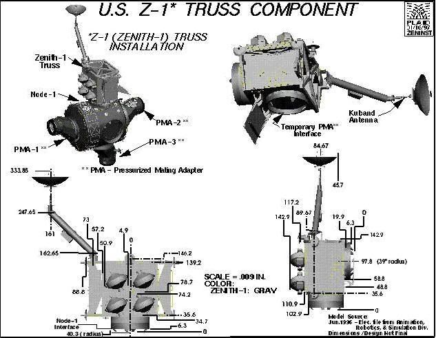
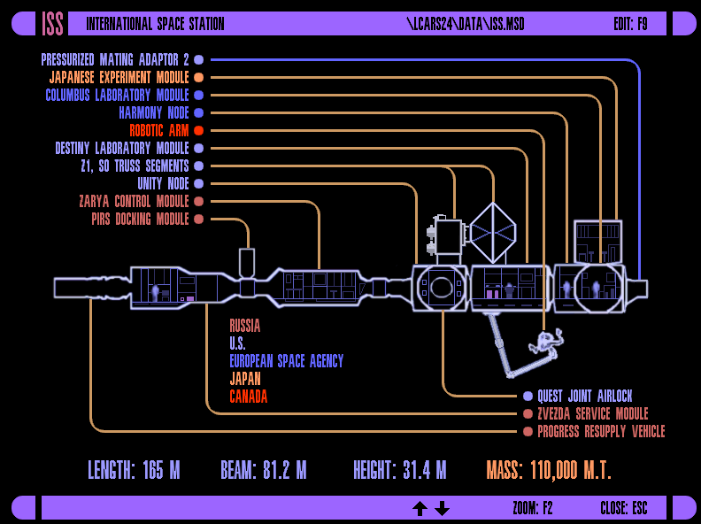
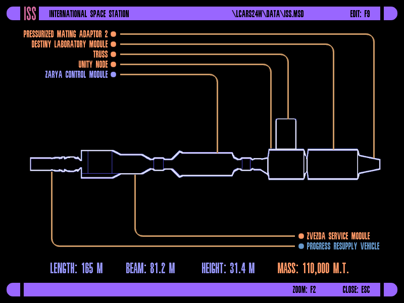
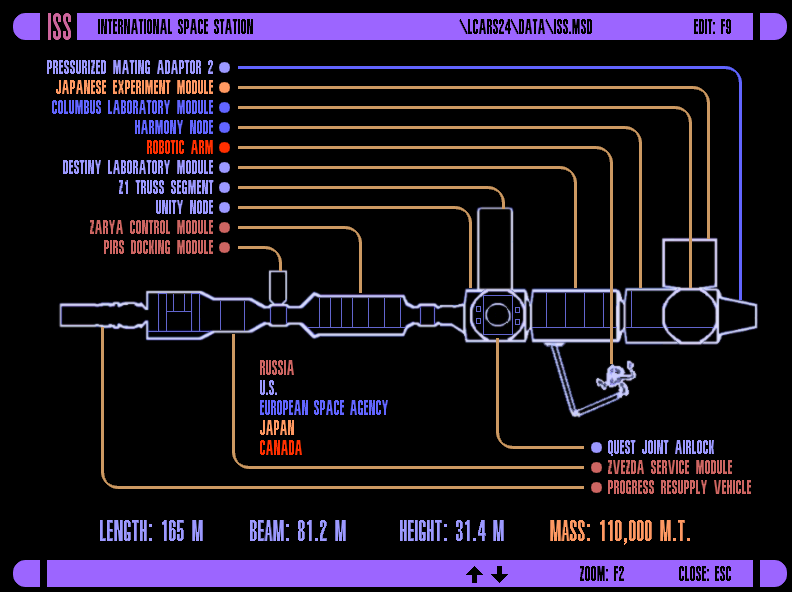
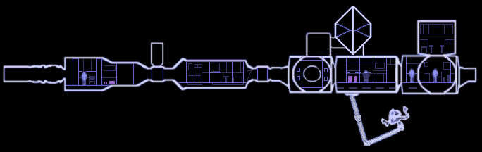
Well, what you have labeled as just simply "Truss" is actually the Z1 (Zenith) Truss. It houses the CMGs (Control Moment Gryros) and the Ku-Band antenea amongst other things.

And on this side (starboard) of the Unity Node, is the Quest Airlock.

And currently, on the nadir port of the Zvesda module, is the Pirs docking module, which will then later be moved to the Zenith port.

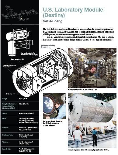
Also on top of the Destiny Lab is the major truss segment starting with the S0, followed by the S1, P1, P3/4, S3/4, P5, S5, P6, S6. But that would have to be done on top-down LCARS view.

But then by the end of the year, you're gonna have the Node 2 "Harmony" on the end of the Destiny Lab, then the Columbus ESA module on the Starboard side of it. With the Japanese Kibo modules on the Port side coming up early next year.
 
Not bad, but just three things.

  1. The Z1 Truss isn't that tall. It's just more or less a square on top of Unity.
  2. Node 2 "Harmony" is too long. It's just 21 feet long. The Destiny Lab by comparison is 28 feet long. So if you got a scale you're using, back it off appropriately. I'd also redesign the PMA 2. Use the same shape you have for PMA 1 on the left side of "Unity", except flip it vertically.
  3. And lastly, go ahead and add the main Truss segment on top of Destiny. Which is shaped like a Hexagon on its tip. In other words, the bottom (attached to Destiny) is one of the points of the Hexagon. And its heighth is just slightly higher than the Z1 Truss.

If you want some really good information of module size and whatnot, go here:
NASA's Multimedia section
Then load up the Interactive Space Station Reference Guide, then select How It Works, and then load up any of the PDFs on the right to get dimensions and all that. The Integrated Truss Assembly one is really good.
 
LCARS 24 said:
Thanks. I'm trying to find the correct end-on shape of the S0 truss element. Various pictures and diagrams disagree. Here's one thing I didn't see before--a Lego model of the ISS but not as up to date as I'm looking for:

http://www.mocpages.com/moc.php/9170

That's a nice LEGO model, but yeah, it's a bit out of date. (Pre-return to flight). But that's alright, NASA hasn't updated their RADAR image they use when docking and undocking. Noticed that Sunday morning when the shuttle undocked.

But do like I suggest. Go to the link I showed above. I'd trust it more than any other source.

OK, with regards to the Truss segments, I found some good pictures that show the back side of the Truss segments:

Rear views
http://spaceflight.nasa.gov/gallery/images/station/issartwork/hires/jsc2006e25651.jpg

http://spaceflight.nasa.gov/gallery/images/station/issartwork/hires/jsc2006e25652.jpg


Front views
http://spaceflight.nasa.gov/gallery/images/station/issartwork/hires/jsc2006e25650.jpg

http://spaceflight.nasa.gov/gallery/images/station/issartwork/hires/jsc2006e25649.jpg

Those two are really good for getting a good look at the Node 2, Columbus, and Kibo labs.
 
Okay, here's what I got from your suggestions and jillions of photos, drawings, and even one mission patch, disorganized as they are (and I resized some Starfleet crewmen from my Defiant MSD and pasted them in--they must be confused right now):

ISS.png
 
LCARS 24 said:
Okay, here's what I got from your suggestions and jillions of photos, drawings, and even one mission patch, disorganized as they are (and I resized some Starfleet crewmen from my Defiant MSD and pasted them in--they must be confused right now):

ISS.png

Are you sure about the shape of the S0 Truss there and its positioning? From the photos I've seen, it's a full Hexagon, with the S1 and P1 being Trapezoidal (see those Rear view shots above). And it's a little further forward than that. More like the bottom mount point should be about where your second bay in the lab is.
 
That's what I thought, too, maybe full looking straight on but half at the ends of this segment. These NASA diagrams get confusing, and many are subject to change.

s0-3D.jpg


Here's one from the other side:

s0-illust.jpg
 
LCARS 24 said:
That's what I thought, too, maybe full looking straight on but half at the ends of this segment. These NASA diagrams get confusing, and many are subject to change.

s0-3D.jpg


Here's one from the other side:

s0-illust.jpg

Huh...

Oh wait...here...here's a real on-flight pic from the back side when the S0 was the only truss up there, and you can clearly see the back-side of the Hexagon that appears in the CG images above.

http://spaceflight.nasa.gov/gallery/images/station/assembly/hires/s110e6058.jpg
 
Great. Thanks for your help. I'm trying to get a release packaged up and didn't know if I could get this in on time. Most of the MSDs I've got are Starfleet, but now I've got three NASA MSDs and want to get some several of the probes in next time.
 
LCARS 24 said:
Great. Thanks for your help. I'm trying to get a release packaged up and didn't know if I could get this in on time. Most of the MSDs I've got are Starfleet, but now I've got three NASA MSDs and want to get some several of the probes in next time.

Well, before you release, you might want to add a bit of detail to the Z1 truss. Looks a bit too plain, compared to the rest of the model.
 
Nice schematic! Are there floors in the ISS? If not, you might want to take them out.
 
No gravity plating, but NASA's published cutaways show floors, as in the one posted above and illustrations of every module like this:

Destiny.jpg


I'll research the Z1 some more.
 
OK, so where's the Ku band antenna?

Also, one more suggestion if I could...

The Canadian Arm II will most likely spend most of its time on the Mobile Base System on the Trusses, rather than underneath the Lab as you got it here.
 
LCARS 24 said:
Okay. I was hoping that would make room for a small top or bottom view, but space is pretty tight.

ISS-1.png

There ya go! I'd say that version makes the ticket.

You ought to submit that image to NASA.

Now then, were you going to add Node 3/Cupola, the Russian Multipurpose Laboratory Module (which is essentially a clone of the Zarya module), and the Docking Cargo Module (which was originally the bottom piece to the now canceled Russian power module).
 
If you are not already a member then please register an account and join in the discussion!

Sign up / Register


Back
Top