Another fan attempt at TOS deck plans

Discussion in 'Fan Art' started by Shaw, Feb 11, 2008.

Thread Status:
Not open for further replies.
  1. Cary L. Brown

    Cary L. Brown Rear Admiral Rear Admiral

    Joined:
    Oct 14, 2005
    Location:
    Austin, Texas
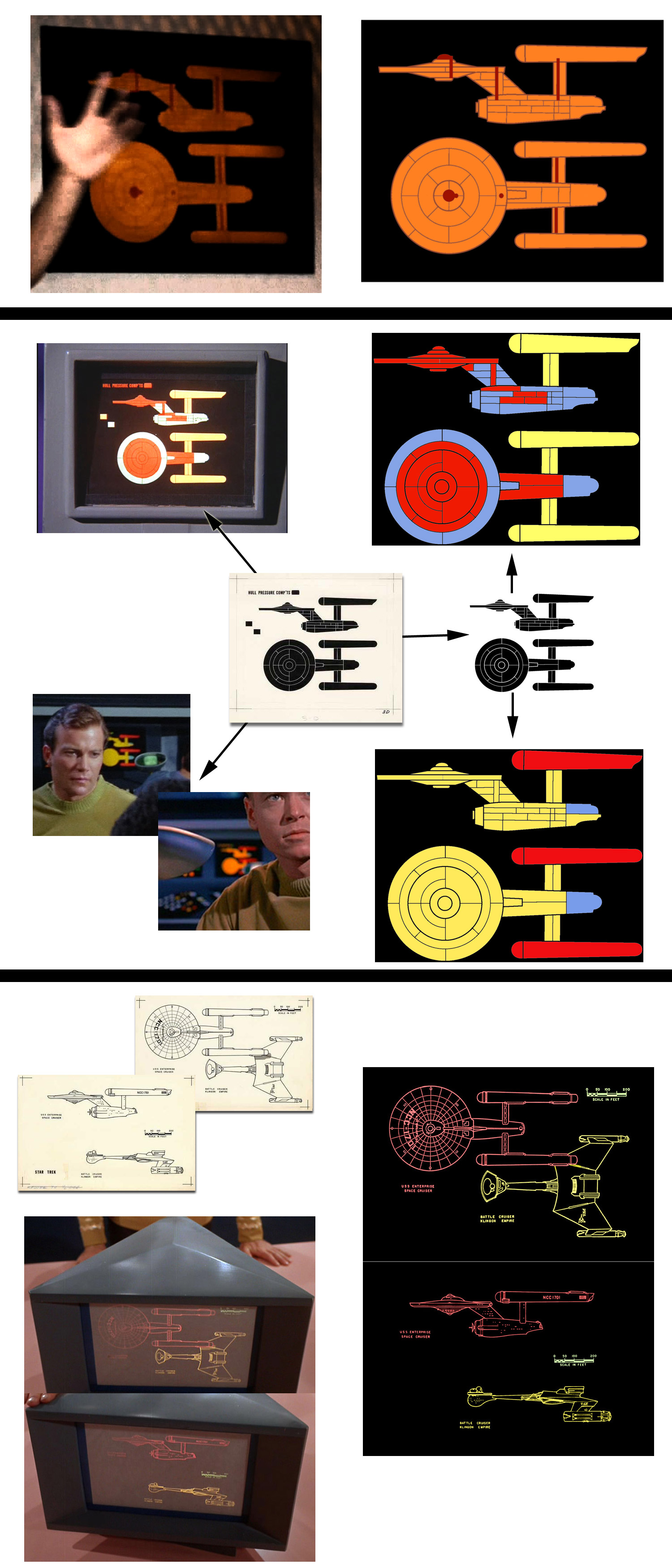
    Basically, in lieu of one of the TOS "canned stock shots" we saw so often, they replaced that shot with one showing the "orbital dockyards" above the starbase. You can see other ships in the distance, and you can see a burned out area at that location on the Enterprise hull, with repair work going on around it.

    I also think that this was just a "light bulb," and that they're just replacing it. The only real place that CRA and I differ is where the ion pod deploys from... he has it leaving the ship at the B/C "teardrop" while I have it being dragged behind the ship from the "red fantail hatch."

    I've always found the "ion pod" to be a pretty silly concept... the major deficiency of this episode, IMHO, was having a MANNED "sensor drone," which is effectively what it is.

    It makes absolutely no sense to have the "pod" be physically attached to the ship (as in how that "bulb" is attached) because there is no way to justify it needing to be "ejected."

    My "best explanation" is that the pod is used to take specialized sensor reading that require isolation from the "background noise" of the ship. So it's basically an unpowered glass sphere with a chair and a sensor suite, and an extremely-low-powered, optically-based (ie, non-interfering) comm device. It literally is dragged behind the ship at a distance, to permit this "limited background noise" operation. Think of it like a submarine's "towed array" in that sense.

    Maybe the issue with it being manned is that, based upon how delicate the readings are, even the noise from a single microprocessor-type device would spoil your readings?

    Anyway, I envision this thing needing to be dragged, not by a "tractor beam" but by a physical cable, some distance behind the ship. In order for that to work, the ship needs to have its deflector shields down (otherwise, the shields would just slice through the tow-cable).

    THAT explains, to me, why this would happen as it did... the Enterprise is just fine handling an "ion storm" with its shields up, but with shields down, she's vulnerable. The ship has standing orders from "Starfleet Silly Science Command" to take uber-accurate readings of ion storms if they encounter them, using this special piece of hardware. This isn't a "starfleet-wide" standing order, just one given to a few (perhaps just one?) ship as an "additiona duty" to support the science division admiral's "pet project?"

    So, the ship is required to put itself at risk, but the idea is to manage that risk. Leave the shields down long enough to get a few readings in the "low-background-noise pod" but retract it in time to get the shields back up and prevent any serious damage from occurring.

    The part that makes NO sense, under any circumstances, is that the guy IN the pod is working without any on-ship support. When Kirk gave the command to recover the pod, it shouldn't have been Finney who was responsible for hitting that particular switch, but in the context of the episode, it was, it seems.

    Since Finney didn't obey the command to "self-recover" when it was given, Kirk had to hit his command chair's "raise the shields" button, which ends up making the ship "safe" but also cuts the tow-cable (and the air supply, fiber-optic communication line, etc) to the pod.

    In normal circumstances, they could just circle around and recover the pod, beam him back aboard, etc, but with an ion storm, they would have a hard time locking on with transporter, or even locating this "no emissions" pod at all... meaning by the time they found it, IF they found it, he'd certainly be dead.

    Until Kirk raised the shields, the ship was essentially like an airplane in a lightning storm... and I'd say that it just happened to catch a single "lightning strike" on that particular running light.

    That's MY take on it. I think it's similar to CRA's.

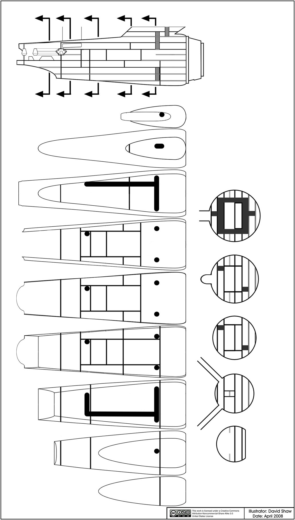
    Now, as for why that item really CAN'T be a manned device... see this:

    [​IMG]

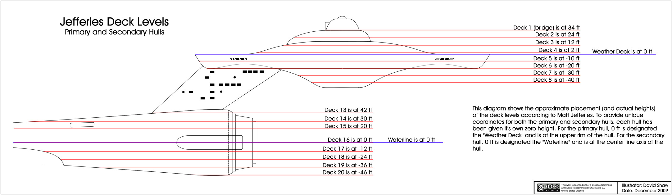
    (And remember, this is on my 1067' long ship... it'll be slightly smaller if you stick with the 947' ship.)

    This could be a dome on the end of a "capsule-shaped coffin" but as a useable working space... not so much. And if it weren't being deployed outside of the ship... Finney would literally be INSIDE THE HULL the entire time anyway, no more or less protected than the bridge crew (with their overhead window) anyway!
     
  2. Shaw

    Shaw Commodore Commodore

    Joined:
    Feb 21, 2007
    Location:
    Twin Cities
    That is as reasonable as any other explanation. I think at the time the writers envisioned something like a crow's nest or the like in a heavy storm. I see a number of parallels in this story with that of one of my favorite movies, The Caine Mutiny.

    But yeah, I envision it being based in the secondary hull too.
     
  3. Captain Robert April

    Captain Robert April Vice Admiral Admiral

    Time to get back to this one, I think....
     
  4. Shaw

    Shaw Commodore Commodore

    Joined:
    Feb 21, 2007
    Location:
    Twin Cities
    Okay... I'll start back on crunching numbers and posting updates on the 11 foot model. Should have something by the end of the weekend.

    I'll also review and post the deck levels as Jefferies saw them for the primary and secondary hulls (though I'll most likely stick with the windows for the levels within the dorsal). Where ever I can I'll attempt to post the raw data (so others can make attempts at figuring out how it might apply).
     
  5. Captain Robert April

    Captain Robert April Vice Admiral Admiral

    Sounds like a plan....
     
  6. Shaw

    Shaw Commodore Commodore

    Joined:
    Feb 21, 2007
    Location:
    Twin Cities
    I know that a lot of people have thought that I picked the deck heights at random or to fit some preconceived ideas I had... this is not true. The positions of the decks are based on figures that Jefferies used in his vision of the Enterprise, which in turn is why I've used them.

    To provide unique coordinates for both the primary and secondary hulls, each hull has been given it's own zero height (0 ft). For the primary hull, 0 ft is designated the "Weather Deck" and is at the upper rim of the hull. For the secondary hull, 0 ft is designated the "Waterline" and is at the center line axis of the hull. The heights for most of the decks are...
    Primary Hull:
    Deck 1 (bridge) is at 34 ft
    Deck 2 is at 24 ft
    Deck 3 is at 12 ft
    Deck 4 is at 2 ft
    0 ft is the Weather Deck
    Deck 5 is at -10 ft
    Deck 6 is at -20 ft
    Deck 7 is at -30 ft
    Deck 8 is at -40 ft

    Secondary Hull:
    Deck 13 is at 42 ft
    Deck 14 is at 30 ft
    Deck 15 is at 20 ft
    Deck 16 is at 0 ft (the Waterline)
    Deck 17 is at -12 ft
    Deck 18 is at -24 ft
    Deck 19 is at -36 ft
    Deck 20 is at -46 ft​
    The dorsal is independent of both hulls and it's deck heights I'll figure out based on studies of the 11 foot model's window placement.

    I've applied the information above to my drafts of the primary and secondary hulls in this diagram.


    This information can be applied to my earlier sketches where this had been left rather vague.
     
  7. Birdog

    Birdog Commander Red Shirt

    Joined:
    Apr 1, 2009
    Location:
    Birdog
    According to that Deck 5 would be really low <7ft due to the outer hull. Am I understanding that right? I'm assuming about 1ft for the hull.
     
  8. Shaw

    Shaw Commodore Commodore

    Joined:
    Feb 21, 2007
    Location:
    Twin Cities
    Well, 1 ft is about right for how Jefferies saw things. But even at 1 ft thick, how would the floor of Deck 5 at -10 only be 7 ft heigh? When I subtract 1 from 10 I get 9. And that would only be in the outer edges, towards the core you get the higher ceilings (as the floor of Deck 4 is 12 ft above the floor of Deck 5).

    From the show, I'd guess the hull thickness to be between 8 to 12 inches...

    [​IMG]

    ...which is about what we see for the shuttlecraft too.

    As for deck heights... the highest ceilings shown were in the corridors and sickbay, but most other rooms were lower (with structural members often being seen).
     
  9. TIN_MAN

    TIN_MAN Fleet Captain Fleet Captain

    Joined:
    Aug 26, 2007
    I have a question on a related note, which I don't think has been brought up yet? I assume when you were looking at the Hull pressure diagram, you also considered the turbo lift diagram as a possible clue to how to proceed for the saucer layout, possibly as an alternative to, or perhaps in addition to, the other? So I'm curious, what was your thought processes in choosing the pressure compartment diagram exclusively?
     
  10. Shaw

    Shaw Commodore Commodore

    Joined:
    Feb 21, 2007
    Location:
    Twin Cities
    Well, it wasn't exclusively... but the diagram says what it is, where as the turbo lift diagram seems intent on showing the turbo lifts (though by the time the series went into production Jefferies (and the producers) wanted it more extensive to get people from place to place better. The other lines aren't denoted, and could be things like corridors or the like.

    As for why use the compartment diagram at all?

    It provides a very nice partitioning of massive decks. Other wise you start with nothing and the question pops up later as to how the compartments come into play. But mainly it was a better starting point than big blank circular decks.

    The top view of the secondary hull in the turbo lift diagram is more helpful though, and if you look at the floor plans of the secondary hull that I've done you might see where I sort of followed that partitioning rather than the other one (which had bulkheads down the center of the hull).

    But again, it is not exclusively used... it is used in concert with a number of other references (Jefferies deck heights, the actual set dimensions, the physical shape of the model, etc.). I'd have reached different conclusions if I ignored any of them or weighted them differently (and other people have obviously reached different conclusions), and my conclusions might change again if I find more data.

    All I'm doing is distilling and refining all the data as I see it... which is why I'm also attempting to make sure people have the data so they can distill and refine it in their own way. I'm not saying (and never have said) that my interpretation is the only one or even the best one.

    All this really is is my best efforts.
     
  11. Birdog

    Birdog Commander Red Shirt

    Joined:
    Apr 1, 2009
    Location:
    Birdog
    You're correct I was looking at deck four and five and did the mental math backwards. You'd have nine feet outboard and 12 feet inboard. That's embarrassing :guffaw:
     
  12. Shaw

    Shaw Commodore Commodore

    Joined:
    Feb 21, 2007
    Location:
    Twin Cities
    This is a long thread, so for those who haven't seen what I was just talking about, here are the diagrams...

    Early secondary hull partitioning...


    And some of the graphics used in TOS (including the hull pressure compartments and turbo lift diagrams)...


    And a better version of the turbo lift diagram can be found here.


    Don't worry about it... you'd be surprised at how often I mix up some of these numbers (and waste a ton of effort before noticing).
     
  13. Birdog

    Birdog Commander Red Shirt

    Joined:
    Apr 1, 2009
    Location:
    Birdog
    It's pretty bad because I'm a drafter by trade and do this stuff everyday at work. Oh well it's the weekend.
     
  14. TIN_MAN

    TIN_MAN Fleet Captain Fleet Captain

    Joined:
    Aug 26, 2007
    Well, by "exclusively" I was mainly refering to the saucer plan, particularly decks 5 and 6, where you use the pressure compartment diagram (in a modified form) for both decks. Anyway, I guess what I was getting at is, did you ever consider using the T/L diagram with its alternate (radial) lines, but modified to have the same number of of rings (0-4) as in the P/C diagram, for pressure compartments on deck 6? Or would this totally screw up your "modular construction" concept for the pressure compartments? Please bear with me, there's a method to my madness.;)
     
    Last edited: Dec 13, 2009
  15. Shaw

    Shaw Commodore Commodore

    Joined:
    Feb 21, 2007
    Location:
    Twin Cities
    The main thing that was missing from the turbo lift version was the double deep compartments just aft of the center core. Even though I haven't illustrated anything in them yet, they become important for rooms that were deeper (radially) than the standard cabins.

    But other than that aspect, the alternating sections wouldn't make that much difference (other than the bulkhead right at the window clusters). A lot of it would just be rotating the compartments.

    But for deck 6 by itself... as it stands now, the compartments enclose both decks 5 & 6 (each compartment being two decks thick) which was needed not to cut a compartment totally in half by a turbo lift tube if the compartment becomes completely closed off (you can go under the tube by dropping down a deck and back up again). The fact that compartments are generally not single decks was sort of important in making them as robust as possible on their own.

    And it made isolated compartments less claustrophobic for me personally. I spent a lot of time imagining what it would be like when the pressure doors close and you're stuck in a compartment not knowing if the rest of the ship is even still habitable and how long you'd be there for. :eek:

    I'm sure there are other ways around this (using the other diagram), but I thought that was a good solution to a number of issues while working within that framework.
     
  16. TIN_MAN

    TIN_MAN Fleet Captain Fleet Captain

    Joined:
    Aug 26, 2007
    Oh okay, Gotcha. I was thinking in terms of each deck having its own compartment rings, so this answers my question, thanks. My thinking was that each diagram might be used to represent the two main decks, 5 and 6 respectively? The P/C diagram would then work nicely as deck five, with its big double compartments for large rooms, and the window clusters would be free of bulkheads. Then, on deck six the T/L diagram allows for the P/C's overlaping with those above, would compansate for structural weakness (like bricks in a wall), especialy in the three outer rings where it's needed most. Then the outermost ring would have bulkheads at the cross quarter locations, neatly explaining why the one lone widow here is off to the side, and also the impulse deck engineering would be enclosed in bulkeads on either side. But yeah, if each P/C is two decks high, then what you have makes sense. :techman:

    Oh, and as far as shafts bisecting entire compartmens, as far as I can tell, this would only happen in aft ring two on deck six, but this is one of the uninhabitable portions where the 'undercut' prevents the deck in rings two and three from attaining full hieght, and are thus used presumably only for piping and wiring, storage etc.?
     
    Last edited: Dec 13, 2009
  17. Wingsley

    Wingsley Commodore Commodore

    Joined:
    Feb 18, 2007
    Location:
    Wingsley
    This is very interesting, but also confusing.

    How do the deck arrangements for the "interconnecting dorsal" neck between the saucer and the engineering hull fit into this? Are you saying the neck is completely divorced from both main hulls?
     
  18. Shaw

    Shaw Commodore Commodore

    Joined:
    Feb 21, 2007
    Location:
    Twin Cities
    Well, the main point being that a number of conditions come into play when arranging everything. Being able to move quickly throughout the ship without turbo lifts, being able to move quickly throughout the ship with turbo lifts, and that when a compartment becomes isolated, the people inside have full use of the compartment rather than having isolated pockets within a compartment. It makes for an interesting logic/geometry problem (and aspects of graph theory could actually be applied), which is what makes it so much fun to play with.

    But in the end, I don't believe that there is only one solution. And because of that I would hope that people wouldn't just see mine and stop considering the other possibilities.

    But yeah, rings two and three on deck six are most likely equipment bays, storage areas and the like.

    I guess I'm confused at how you are confused. :wtf:

    I stated that I'm not addressing the dorsal decks here, but will work on nailing them down when I have more information and have done more analysis. That information will come from an as yet incomplete study of the 11 foot model.

    So are you saying that I should not post anything until I have everything completed?

    But the dorsal is the dorsal. It isn't the primary hull and it isn't the secondary hull. There are plenty of sketches of the dorsal that I've posted in the past (like this), but I guess I don't see what is so confusing about not spending time discussing something that wasn't the point of what I was talking about.

    Unless I'm missing something in how you are missing something in all this. :shifty:

    Of course if the question is about which coordinate system the dorsal decks would use... neither. But then again, I'm not doing plans for the ship as a whole.. I'm doing plans for the subassemblies which when put together give you a whole ship (which is most likely how it would have been constructed). The dorsal decks with have their own height callouts because when I look at the dorsal, it'll just be the dorsal at that point (just like when I look at the primary hull, it is just the primary hull, and when I look at the secondary hull, it is just the secondary hull).

    And all three pieces (primary hull, dorsal and secondary hull) are further broken up into smaller pieces by compartments (the dorsal has a number of compartments too). Compartments are assembled to make the major components, and the major components are assembled to make the ship as a whole.

    I've seen other people try to take the ship as a whole... and choke :eek: . I would rather take it as nice bight size pieces. :techman:
     
  19. USS Mariner

    USS Mariner Rear Admiral Rear Admiral

    Joined:
    Jul 11, 2004
    Location:
    Homestate of Matt Jefferies
    Welcome back! When did you figure out how the pilot dome was shaped?
     
  20. Wingsley

    Wingsley Commodore Commodore

    Joined:
    Feb 18, 2007
    Location:
    Wingsley
    No, I wasn't suggesting a course of action. I was just puzzled by how you were planning to fit all the pieces of this jigsaw puzzle together. I agree that it looks like a daunting task.
     
Thread Status:
Not open for further replies.