-
Welcome! The TrekBBS is the number one place to chat about Star Trek with like-minded fans.
If you are not already a member then please register an account and join in the discussion!
You are using an out of date browser. It may not display this or other websites correctly.
You should upgrade or use an alternative browser.
You should upgrade or use an alternative browser.
Another fan attempt at TOS deck plans
- Thread starter Shaw
- Start date
- Status
- Not open for further replies.
Got nacelles?

If I get some free time this week, I'll start compiling my notes into some drawings.Got nacelles?
But be warned, these are drawings of the physical model. If you want them to reflect the fictional ship, they'll need some alterations.
Just need a good starting point.
I've started in on the drawings of the nacelles... all of these are at 1/4 scale to the original model.
My (obvious) first goal is to finish my studies of the 11 foot model. After that I'll apply Jefferies' deck placement so that the boundaries of the decks match the hull's curves correctly), followed by a redrawing of the scaled set plans from the series. And as stated up thread, I'll be leaving two and three wall sets as two and three walled sets. It'll be up to who ever used this info to decide on their own where they want to place the walls we didn't see on screen (and weren't there on set anyways).
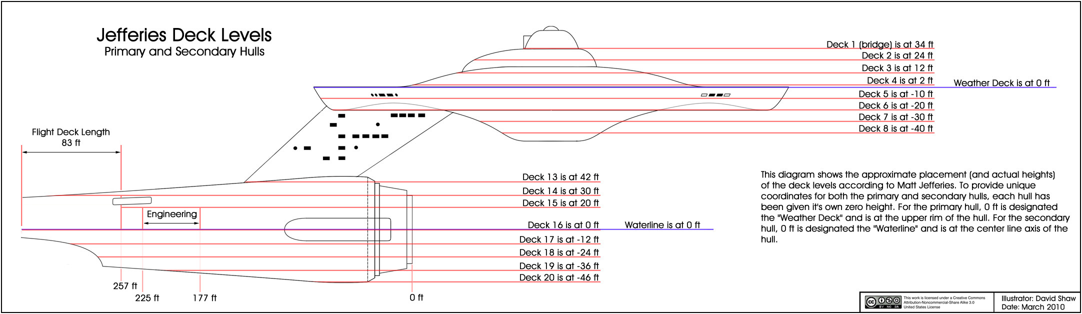
And I'll throw together a collection of the measurements that Jefferies used when thinking about this stuff as well. And because it has been updated a couple times, I'll repost this illustration...
I'll also review the sketches posted in this thread to date and put together a collection of which ones are still relevant (or useful).
Sorry if this has seemed awfully slow lately. This stuff doesn't pay the bills, and the bills still need to be paid.
My (obvious) first goal is to finish my studies of the 11 foot model. After that I'll apply Jefferies' deck placement so that the boundaries of the decks match the hull's curves correctly), followed by a redrawing of the scaled set plans from the series. And as stated up thread, I'll be leaving two and three wall sets as two and three walled sets. It'll be up to who ever used this info to decide on their own where they want to place the walls we didn't see on screen (and weren't there on set anyways).
And I'll throw together a collection of the measurements that Jefferies used when thinking about this stuff as well. And because it has been updated a couple times, I'll repost this illustration...
I'll also review the sketches posted in this thread to date and put together a collection of which ones are still relevant (or useful).
Sorry if this has seemed awfully slow lately. This stuff doesn't pay the bills, and the bills still need to be paid.
Thanks!
I got slammed with a ton of work recently, so I'm running a little behind schedule on the nacelle drawings, I'll try to have them up soon
I got slammed with a ton of work recently, so I'm running a little behind schedule on the nacelle drawings, I'll try to have them up soon
I mainly use Create and Photoshop for my sketches. I haven't decided yet on how I might release final versions, but all the preliminary stuff will most likely stay as JPEG... though I do try to make anything that I know might be useful to others as high resolution as possible.Hey Shaw, what tool/program are you using for these illustrations?
Do you think you could upload a vector version of these concepts/mockups?
So while sitting at a client's system watching progress bars (similar to watching grass grow), I noticed a number of people discussing the "947 foot" Enterprise. As a general reference (that is, talking in vague terms) that is fine... but when people actually attempt to apply that one length to either of the models as a scale reference, then you are going to have issues.
Matt Jefferies drew up the plans for the original models, and for the most part assumed that the builders of the models followed his plans. But the thing is, the first (33 inch) model was started before the final plans were finished, and the second (11 foot) model was built in three weeks. Add to that the fact that the Enterprise is not a single piece, but is actually four pieces arranged together, and using the model's actual dimensions becomes an issue.
So, now that I've brought it up, how do we deal with this issue?
First things first... throw out the 947 foot length when discussing the models.
Jefferies' plans on the page were 33.75 inches in length, the 33 inch model (from my research) appears to be 33.67 inches in length, and at one-quarter scale the 11 foot model is about 33.5 inches in length. So right there... overall length wasn't preserved between the original plans and the models, and no one should really be surprised by this.
But Jefferies gave us additional dimensions of the four main pieces. The primary hull has a diameter of 417 feet, the secondary hull has a length of 340 feet, and the nacelles are each 504 feet in length. I have generally considered the primary hull as the gauge for everything else as it is primary, though I totally understand the argument for using the length of the secondary hull (as it's length was preserved in Jefferies' drawings of the Phase II Enterprise).
So if we equate 417 feet with 15 inches (the diameter of the primary hull on the original plans), the length of the secondary hull would end up at 12.23 inches and the length of the nacelles would end up at 18.13 inches. On the page, Jefferies original plans had the secondary hull at 12.125 inches and the nacelles at 18.125 inches.
What about the 11 foot model?
As everyone seems to want to use the 11 foot model as the template for the exterior of the Enterprise, we should make note of it's dimensions compared to the original plans... noting that the 11 foot model was to be built at 4 times the dimensions of these original plans. At one-quarter scale, the diameter of the primary hull is 14.8125 inches, the length of the secondary hull is 12.25 inches, and the length of the nacelles are 18.0625 inches.
If we go with how I plan to proceed (using the primary hull diameter as a gauge), we end up with a secondary hull that is 344.9 feet in length (almost 5 feet longer than Jefferies' 340 feet) and nacelles that are 508.5 feet in length (4 and a half feet longer than Jefferies' 504 feet). And when assembled, the 11 foot model comes out to 943.65 feet long (a little more than 3 feet short of Jefferies' 947 foot over all length).
The other reason for using the primary hull diameter as a gauge for scaling is that it worked out nicely for both the original plans and my replica of the original model. 417 feet is 5004 inches. That means that 15 inches (the diameter of the primary hull on the original plans) is almost exactly 1/333 scale, and 10 inches (the diameter of my model) is almost exactly 1/500 scale.
Additionally, though I'm pretty sure no one is going to understand what I mean by this, I have been looking at all this sort of like the Knapsack Problem. That is to say, I give certain data points a value... and when I have to make a choice between conflicting data I pick the data with the higher value.
In all actuality, we all do this when looking at this puzzle to some degree, we just don't all apply the same values to the different data. And that is why even with all the same data we can still end up with significantly different versions of the Enterprise. One of the things I put the least value on are ideas that I've come up with on my own... which are almost always the first things to go as I get more data. For others, that is the fun part (adding their own signature to their designs), but in the end I'm really only concerned with what Jefferies was thinking of back when Star Trek was being made.
I don't think that the 947' length was what he was originally aiming for... and at 33.75 inches the ship would have been 938.25'. So I think when the drawings we saw (with all the dimensions on it) was drawn up for series production (1966), Jefferies was most likely aware that the components were placed differently on the models than on his original plans. Had the original plans been slightly over 34 inches in length, then I would have thought that it was part of his original intent. As it stands, only the component sizes reflect his original scaling from 1964, the overall length was most likely a casualty of the rush to finish the models for the first pilot.
At the time (fall of 1964), I think the only thing that really mattered was that the bridge dome diameter work with the bridge dome set plans (the bridge set construction was started after the 33 inch model was started, and filming of the bridge set scenes were finished before the 11 foot model was started).
The one aspect of his original design he seemed to not want to let go of was how far apart the nacelles were from each other... either he didn't know that they were moved closer together on both models or he didn't care for the fact that they were moved together.
I personally think they look better closer together.
Of course anyone wanting exactly 947 feet can just move the nacelles back slightly on their supports... I doubt anyone would notice.
Or, just upsize the drawings a tad so that the ship clocks in at 947' in length, regardless of what that does to the size of the components. Since that results in greater interior room, I don't see any downside.
Speculation on my part but how far out of true would the measurements be if the nacelles were only supporting themselves? IOW, would they torque at all under the pull of gravity? Toe in at the caps and toe out on the aft ends? Enough to account for a disparity in measurements? Especially if you were having someone re-measure the ship for you...The one aspect of his original design he seemed to not want to let go of was how far apart the nacelles were from each other... either he didn't know that they were moved closer together on both models or he didn't care for the fact that they were moved together.
I personally think they look better closer together.
Just a random thought I had reading your post.
Seems like a slippery slope to me... a little upsizing here, a little rescaling there, next thing you know you've got JJ's Enterprise.Or, just upsize the drawings a tad so that the ship clocks in at 947' in length, regardless of what that does to the size of the components. Since that results in greater interior room, I don't see any downside.

As I said, everyone is free to do whatever they want. But for me, Jefferies' design intent has more weight than almost any other data or idea.
Actually, the models are very sturdy. Only the port nacelle of the 11 foot model was out of alignment, and that was due to the additional weight from the inner trench.Speculation on my part but how far out of true would the measurements be if the nacelles were only supporting themselves? IOW, would they torque at all under the pull of gravity? Toe in at the caps and toe out on the aft ends? Enough to account for a disparity in measurements? Especially if you were having someone re-measure the ship for you.
The reason the nacelles are significantly different from Jefferies design is that the point where the supports meet the nacelles is quite a bit lower than what most people expect (specially if you've ever built any of the AMT kits).
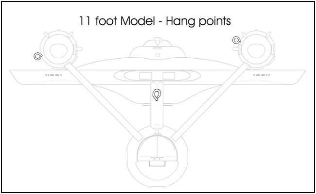
Something to keep in mind... for many years the 11 foot model was suspended by it's nacelles. So not only where they not being effected by supporting themselves, they were staying true even while supporting much of the rest of the model.
And remember... if the nacelles were rotating due to torque on the supports enough that the measurements would be off by nearly 5 inches, then everything about the nacelles would be tilted too (rather than straight up and down).
It was a significant change from the plans, and was done on both models. But Jefferies never reflected that change in his later drawings.
I do have a theory as to why it was done... but I'll wait until I have some free time to discuss it at length.
IIRC, the original idea was for the pylons to be at a 45 degree angle. For the three-foot model, that might work, but the eleven footer, I suspect the fear was that those puppies'd be sagging in no time, if not snap off entirely, so a slightly shallower angle (about two degrees higher on each side) was chosen, to keep the nacelles from the tipping point. And since the smaller model was really just a proof-of-concept piece, it makes sense that both models would reflect this change.
Sound 'bout right?
Sound 'bout right?
Well, first of all... the supports are solid wood, and would most likely hold my weight (210 lb.) without any noticeable sag. The area where they connect to the secondary hull was so re-enforced that all they do is slide into the openings and fit perfectly snug. The front third of the nacelles were originally solid wood as well (later drilled out for the dome motors), and the supports are held in place with two 3.5 inch screws for each nacelle.
The thing is, not only were the supports over engineered for the task of supporting the nacelles, for most of the life of the 11 foot model, the stresses on the supports have been fully reversed as the model was hanging from it's nacelles.
The major difference in the placement of the nacelles most likely happened when Datin was test fitting the 33 inch model's components. Before adding any of the details to the parts, he most likely noted that the nacelles worked better when swapped. In the following diagram I show the Enterprise as planned by Jefferies, and the Enterprise assembled by Datin (which only required a switching of the port and starboard nacelles, and a shortening of the supports for them to be at the same height as the original plans).
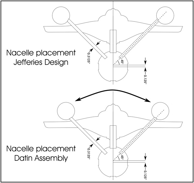
That not only puts the nacelles in almost the exact position that they are in on both the 33 inch and 11 foot models, it also almost exactly matches the connection point of the supports on both models as well.
I'm sure that few people would be interested in this, but I'm mapping out all the pieces of wood used to make the secondary hull (inside and out) and where holes were drilled/cut to allow for lighting of the model. I'll be outlining that stuff after I finish with my notes on the nacelles.
The thing is, not only were the supports over engineered for the task of supporting the nacelles, for most of the life of the 11 foot model, the stresses on the supports have been fully reversed as the model was hanging from it's nacelles.
The major difference in the placement of the nacelles most likely happened when Datin was test fitting the 33 inch model's components. Before adding any of the details to the parts, he most likely noted that the nacelles worked better when swapped. In the following diagram I show the Enterprise as planned by Jefferies, and the Enterprise assembled by Datin (which only required a switching of the port and starboard nacelles, and a shortening of the supports for them to be at the same height as the original plans).
That not only puts the nacelles in almost the exact position that they are in on both the 33 inch and 11 foot models, it also almost exactly matches the connection point of the supports on both models as well.
I'm sure that few people would be interested in this, but I'm mapping out all the pieces of wood used to make the secondary hull (inside and out) and where holes were drilled/cut to allow for lighting of the model. I'll be outlining that stuff after I finish with my notes on the nacelles.
Shaw
Buy the time you are fininshed you will have a Manual that will Eclipse the Haynes manual keep up the great work ")
Buy the time you are fininshed you will have a Manual that will Eclipse the Haynes manual keep up the great work
I'm surprised no one noticed this before.
- Status
- Not open for further replies.
Similar threads
- Replies
- 2
- Views
- 1K
- Replies
- 0
- Views
- 322
- Replies
- 192
- Views
- 28K
If you are not already a member then please register an account and join in the discussion!