-
Welcome! The TrekBBS is the number one place to chat about Star Trek with like-minded fans.
If you are not already a member then please register an account and join in the discussion!
You are using an out of date browser. It may not display this or other websites correctly.
You should upgrade or use an alternative browser.
You should upgrade or use an alternative browser.
BLSSDWLF's TOS Enterprise WIP
- Thread starter blssdwlf
- Start date
@Gagarin - thanks!
@Mytran - Nice") I'll give those pics a shot and see what number range I come up with.
I'll give those pics a shot and see what number range I come up with.
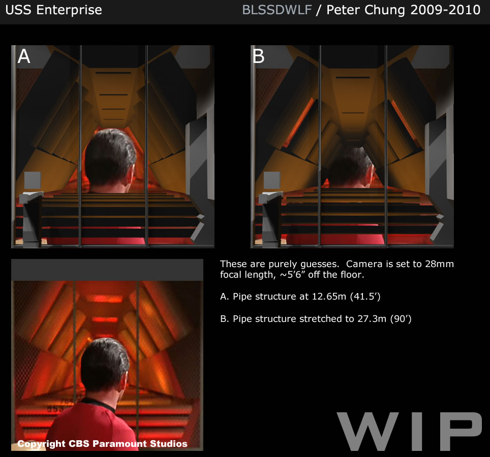
Did you guys know that the Enterprise had a fancy vertical warp core?
Just kidding
It's that big vertical pipe/conduit structure that Evil Kirk blasts with his phaser. I haven't worked out it's location yet and the camera never pans up to know what it looks like above 7' - so it's conjectural as to what the top half looks like.
I also tightened up the dimensions with Mytran's help and the room from front wall to back wall is now 24' long.

@Mytran - Nice
I'll give those pics a shot and see what number range I come up with. Did you guys know that the Enterprise had a fancy vertical warp core?
Just kidding
It's that big vertical pipe/conduit structure that Evil Kirk blasts with his phaser. I haven't worked out it's location yet and the camera never pans up to know what it looks like above 7' - so it's conjectural as to what the top half looks like.
I also tightened up the dimensions with Mytran's help and the room from front wall to back wall is now 24' long.
here's an idea that might work.
when I saw Shaw's illustration it reminded me of a diagram that was mounted on the main engine control board on the ship I served on in the Navy. The ship, USS MARS, had a large engine room amidships with a single shaft running aft through a narrow series of rooms (shaft alley) to the screw. That ER and shaft alley were represented on the diagram.
only i figured two engines, two shaft alleys.
Looks great! looks like you nailed the design of the "vertical warp core" (or whatever). Although the "flanges" around the bottom of the pipe should probably be around the top as well? As you probably know, the big red "struts" of this set piece were left over from the support colonnade of the pilot ep's circular briefing room, and the central "core" was also seen (as two seperate pieces) as columns in the phaser room set in "Balance of Terror". This same set piece (the column) was also used again in "The Devil in the Dark" as part of the pergeum reactor, where the ends were spliced back together where it had been cut in half, after which it appears yet again in the Constellations' engine room in "The Doomsday Machine" (in a similar spot on the far right of the set, looking aftward. Maybe these referances can help you narrow down the "best look" of this thing, although what you already have is superb!
Last edited:
Hey blssdwlf, where's your pic gone? I saw it briefly at work today but now I have the chance for some proper scrutiny - poof! From what I remember it looked great, hopefully you are just making some adjustments.
BK613's idea is a good way to combine the two Engine Rooms, although if you want to be accurate to the sets the season 1 version should be longer than than the later one. Unfortunately the Star Trek Magazine does not make this clear, since they were trying to argue that it was the same room, just with some refitting. Given their different room shapes this would be quite a feat of ... engineering
However, if set accuracy isn't too much of an issue for you then no problem and the layout is fine as it is. I particularly like the way you've left enough room for a proper sized Emergency Manual Monitor.
TIN MAN did a great multiple Engine Room setup recently - care to plug it again?")
BK613's idea is a good way to combine the two Engine Rooms, although if you want to be accurate to the sets the season 1 version should be longer than than the later one. Unfortunately the Star Trek Magazine does not make this clear, since they were trying to argue that it was the same room, just with some refitting. Given their different room shapes this would be quite a feat of ... engineering
However, if set accuracy isn't too much of an issue for you then no problem and the layout is fine as it is. I particularly like the way you've left enough room for a proper sized Emergency Manual Monitor.
TIN MAN did a great multiple Engine Room setup recently - care to plug it again?
as long as interior bulkheads aren't load-bearing members, then it would be possible. the two-engine room arrangement has the advantage of explaining the reused ER footage, especially the Scotty Grate Grab.Mytran;4033149[B said:BK613[/B]'s idea is a good way to combine the two Engine Rooms, although if you want to be accurate to the sets the season 1 version should be longer than than the later one. Unfortunately the Star Trek Magazine does not make this clear, since they were trying to argue that it was the same room, just with some refitting. Given their different room shapes this would be quite a feat of ... engineering
Not sure if this was directed at me but my iso view doesn't do the EMM room's width justice; it is wider on the cross-section. it will probably be corrected the next time I mess with this image.Mytran;4033149However said:.[/I]
Mytran;4033149[B said:TIN MAN[/B] did a great multiple Engine Room setup recently - care to plug it again?
I'd like to see that as well; a dying motherboard has kept me from being very active lately and I have missed a bunch of stuff (especially images; most image-hosting sites are blocked at work.)
Here's the linky...
http://i49.tinypic.com/2qjvup0.jpg
Keep in mind this was based on Shaw's internals, which he evidently has revised, but it's still workable, I guess?
The basic idea is very similar to BK613's, but with the addition of the TAS engine rooms and corresponding tube tunnel on the C/L.
http://i49.tinypic.com/2qjvup0.jpg
Keep in mind this was based on Shaw's internals, which he evidently has revised, but it's still workable, I guess?
The basic idea is very similar to BK613's, but with the addition of the TAS engine rooms and corresponding tube tunnel on the C/L.
Last edited:
Here's the linky...
http://i49.tinypic.com/2qjvup0.jpg
Keep in mind this was based on Shaw's internals, which he evidently has revised, but it's still workable, I guess?
The basic idea is very similar to BK613's, but with the addition of the TAS engine rooms and corresponding tube tunnel on the C/L.
Ooh I like that! Nice use of the TAS stuff.
as long as interior bulkheads aren't load-bearing members, then it would be possible.Mytran;4033149[B said:BK613[/B]'s idea is a good way to combine the two Engine Rooms, although if you want to be accurate to the sets the season 1 version should be longer than than the later one. Unfortunately the Star Trek Magazine does not make this clear, since they were trying to argue that it was the same room, just with some refitting. Given their different room shapes this would be quite a feat of ... engineering
Possible, yes. Desirable?...
I quite agree. I'm strongly of the opinion that there were at least two Engine Rooms on the Enterprise.the two-engine room arrangement has the advantage of explaining the reused ER footage, especially the Scotty Grate Grab.
Not sure if this was directed at me but my iso view doesn't do the EMM room's width justice; it is wider on the cross-section. it will probably be corrected the next time I mess with this image.[/QUOTE]Mytran;4033149However said:.[/I]
Actually, I thought it was fine!
Here's the linky...
http://i49.tinypic.com/2qjvup0.jpg
Keep in mind this was based on Shaw's internals, which he evidently has revised, but it's still workable, I guess?
The basic idea is very similar to BK613's, but with the addition of the TAS engine rooms and corresponding tube tunnel on the C/L.
Ooh I like that! Nice use of the TAS stuff.
Thanks, glad you like it.
Sometimes form must follow function...as long as interior bulkheads aren't load-bearing members, then it would be possible.Unfortunately the Star Trek Magazine does not make this clear, since they were trying to argue that it was the same room, just with some refitting. Given their different room shapes this would be quite a feat of ... engineering
Possible, yes. Desirable?...
ER Comparison
I quite agree. I'm strongly of the opinion that there were at least two Engine Rooms on the Enterprise.the two-engine room arrangement has the advantage of explaining the reused ER footage, especially the Scotty Grate Grab.
Two ERs that close together IMO
well had some other thoughts about it as well, such as having the space under the EMM be open instead of enclosed on the new room side. And the corridor to the old room be normal corridor height, suggesting that it was originally an outer corridor..Actually, I thought it was fine!Not sure if this was directed at me but my iso view doesn't do the EMM room's width justice; it is wider on the cross-section. it will probably be corrected the next time I mess with this image.However, if set accuracy isn't too much of an issue for you then no problem and the layout is fine as it is. I particularly like the way you've left enough room for a proper sized Emergency Manual Monitor.
Thanks everyone for the ideas and the references.
@Mytran - let me know if the image is still not coming up for you as it is coming up for me now. It might have been a hiccup at my webhost.
@TIN_MAN - thanks for the hints at which episodes that prop was re-used I'll take a look for ideas and at the very least get to re-use the model (just virtually)
@BK613 and TIN_MAN - those are pretty cool ideas for the double-room arrangement. I was thinking that the season 2 engine rooms could be side-to-side. I'm not so sure that the season 1 engine room would work next to a season 2 as Mytran points out they are different lengths and as I just realized that they are also different heights. The season 2 ER is a few feet higher than the season 1 ER.
A speculation: Perhaps the Season 1 ERs were replaced sometime in late Season 1/early Season 2 when they streamlined the dilithium circuit and energisers away from the room and placed it in the middle (and probably under) the floor of the ER...
I do want to tie in the corridors as seen in the episodes and "The Naked Time" unfortunately shows the S1 ER along a very long curved corridor I'm okay with a short curved corridor as I can still put that in the engineering hull, but the super long one that makes it a bit tougher (even if I make it less curvy )
PS. Am I the only one that thinks that vertical pipe conduit thing looks like a larger version of the vertical podium pipe thing that Spock fiddles with at the end of Wrath of Khan to get the mains back online?
@Mytran - let me know if the image is still not coming up for you as it is coming up for me now. It might have been a hiccup at my webhost.
@TIN_MAN - thanks for the hints at which episodes that prop was re-used
I'll take a look for ideas and at the very least get to re-use the model (just virtually) @BK613 and TIN_MAN - those are pretty cool ideas for the double-room arrangement. I was thinking that the season 2 engine rooms could be side-to-side. I'm not so sure that the season 1 engine room would work next to a season 2 as Mytran points out they are different lengths and as I just realized that they are also different heights. The season 2 ER is a few feet higher than the season 1 ER.
A speculation: Perhaps the Season 1 ERs were replaced sometime in late Season 1/early Season 2 when they streamlined the dilithium circuit and energisers away from the room and placed it in the middle (and probably under) the floor of the ER...
I do want to tie in the corridors as seen in the episodes and "The Naked Time" unfortunately shows the S1 ER along a very long curved corridor
I'm okay with a short curved corridor as I can still put that in the engineering hull, but the super long one that makes it a bit tougher (even if I make it less curvy )PS. Am I the only one that thinks that vertical pipe conduit thing looks like a larger version of the vertical podium pipe thing that Spock fiddles with at the end of Wrath of Khan to get the mains back online?
Last edited:
Yes, that is the other solution to this problem (and also the one that Franz Joseph adopted, so it's got a good history!) If nothing else, it solves the viewing issues.
Do you have an in-universe explanation as to the mechanical reasoning behind the tapering shape?
Well, in order to answer the question let me review my thought process. My project is a slow going affair that I start and stop on for a few years now. I started it waaay back in 2005. My goal to make a set of deck plans for the TOS E that fit exactly what was shown on screen, to my best ability to reconcile it all. My mantra is "What would the Thermians do?" in reference to the aliens from Galaxy Quest who innocently thought the show was real and managed to build a working replica based on images from the show.
Anyway, I got through so far a little over half the first season watched with a notebook in hand, drawing out each set as filmed and making notes as to which direction characters entered or left and where dialogue says they came from or are going to, the idea being to glean some clues as to how the various locations relate to each other in the volume of the ship. Now, given that I'm not quite 1/5 through the source material, I don't know if it's even possible to make any use of all this info, but it's fun for me just the same.
As far as the engine room goes, there are enough shots on "engine room" areas where the sets were obviously arranged out of wild sections on the morning of the shoot, where, to take all of this literally, there are probably dozens of separate engine room areas. This makes sense as there are dialogue references to the engineering sections being maze like and easy to hide in ("Court Martial") and various episodes where "engineering sections" are referred to as distinct from the regular deck space.
Also, there are shots in different episodes where the tapered pipe unit is seen surrounded by other walls and machinery arranged differently. My current working thesis is that those tapered pipes are essentially some form of power transformer where, on the bigger end, the power is lower voltage and on the small end, power is high voltage. Raw power comes into the unit at the small end and comes back out of the large end in a form more useful for the lower power needs of the ship's general equipment.
This research intensive project grew out of an earlier attempt to come up with deck plans. The multiple "engineering rooms" theory was the starting point for this project. Here:

is a thumbnail to go to a early idea I had for Deck 5. This is NOT the direction I'm going in for my current project, but it does illustrate one possible arrangement of multiple engine rooms with the tapered pipes being a power transformer instead of an engine component. My idea was that there is at least one episode where power is cut on one half of the ship, then the other. So I put one Engineering Room in each half of the ship in approximately the 1:00 and 5:00 positions. There would also be more of these types of room in the lower hull.
Anyhow, that's my idea, in more detail than I'm sure anyone bothered to read...

--Alex
P.S. I used the hull pressure diagram to divide up the volume before i ever saw any of Shaw's work.. That he used the same approach really got me to pay attention to his thread and my current ideas are at least influenced by his work. Great stuff!
Last edited:
Thanks blssdwlf, the pics are coming up well now! Where did you get the information that the S2 room is taller? I must admit I mostly work in 2-D so haven't noticed!
Inserting the log curved corridor causes all sorts of headaches, although I have come up with a couple of different solutions which I'll try and dig up. For reference, the radius is 50'3" to the outer wall (there is a very good reason for this seemingly odd distance)
Albertese, you have the same approach to Enterprise construction as me! My first draft of the "just what you see on screen" Enterprise was done back in University and it's only since joining this board that I have dusted off the project for a second (and more accurate) version. It will be very interesting to see how our versions turn out (and differ!) Like you I am also going through the exhaustive process of watching and documenting each episode - but you know it's worth it!
Thanks blssdwlf, the pics are coming up well now! Where did you get the information that the S2 room is taller? I must admit I mostly work in 2-D so haven't noticed!
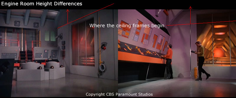
@Mytran - Yep I wouldn't have noticed either until I started putting together the ceiling parts. You can see in the screenshots below that the ceiling framework starts a few feet lower in the S1 engine room. It looks like when they added that balcony they had to move up the framework.
@Albertese and Mytran - Ahahaha
"What would the Thermians do?" is pretty much the same motto I'm using for this too! Can I use that in my signature? (Although I'm willing to alter the curve of the corridors and do small tweaks though
)One thing I've found through building out these structures is that it does put some interesting limits on where they can go in the ship (especially the 947' version). Even if we use the lower height S1 ER in the primary hull, the sheer height of the room + the height of the pipe structure limits it to somewhere close to the center of the ship and not the rim near the impulse engine area. The rim is too thin and the undercut really prevent any placement far away from the center.
@Mytran - forgot to write that I'm getting a 64' radius to the outer wall in my model.
Well spotted on the ceiling height differences, I can't believe I never saw that!
Regarding the corridor measurement, that 64' wouldn't be a reference to RADIUS TO RADIAL BEAM 64'9" would it?
That distance actually refers to the midway beam inside the briefing room and is backed up by the numerous other measurements and 8' panels listed on the same drawing:

Using that 64'9" line as a scale, I deduced that the radius of the corridor was 50'3" and the radius to the inner briefing room wall was 52'7. Since I brought Cary up, it's worth mentioning that this is where I think he made an error in his reconstructed measurements. He stated that he the measurement to the inner wall was 55'7" but this is incompatible with the 63'9" and other measurements on that page.
Having said all that - maybe this is not the reason you picked 64' after all! In which case, carry on.
Regarding the corridor measurement, that 64' wouldn't be a reference to RADIUS TO RADIAL BEAM 64'9" would it?
That distance actually refers to the midway beam inside the briefing room and is backed up by the numerous other measurements and 8' panels listed on the same drawing:
Using that 64'9" line as a scale, I deduced that the radius of the corridor was 50'3" and the radius to the inner briefing room wall was 52'7. Since I brought Cary up, it's worth mentioning that this is where I think he made an error in his reconstructed measurements. He stated that he the measurement to the inner wall was 55'7" but this is incompatible with the 63'9" and other measurements on that page.
Having said all that - maybe this is not the reason you picked 64' after all! In which case, carry on.
Last edited:
@Mytran - Good question! I hadn't seen that stage plan before so it came from measuring my model. I went and looked back at the 64' and I realized that I never updated my corridor model with the new 8' wide corridor scaling information  .
.
I am using the S2 "Journey To Babel" stage plan for the layout and created a circle matching the curvature of the corridor so I can center the image for use in Lightwave.
(I overlayed the S1 "Balance of Terror" stage plan you uploaded earlier - very helpful!)

and with new information, I re-scaled the plan in Lightwave till I matched the corridor width of 8' and S2 Engine Room front wall to back wall length of 20'.
The distances I am now measuring are...
center to near corridor wall = 43.8'
center to far corridor wall = 51.8'

Granted I could be off a bit on the radius with the diagram and I'm okay with that as they're really to provide positioning information. I think as long as I get the individual rooms correct, I can place them on any curve necessary to approximate a room closer or further away from the center
. I am using the S2 "Journey To Babel" stage plan for the layout and created a circle matching the curvature of the corridor so I can center the image for use in Lightwave.
(I overlayed the S1 "Balance of Terror" stage plan you uploaded earlier - very helpful!)
and with new information, I re-scaled the plan in Lightwave till I matched the corridor width of 8' and S2 Engine Room front wall to back wall length of 20'.
The distances I am now measuring are...
center to near corridor wall = 43.8'
center to far corridor wall = 51.8'
Granted I could be off a bit on the radius with the diagram and I'm okay with that as they're really to provide positioning information. I think as long as I get the individual rooms correct, I can place them on any curve necessary to approximate a room closer or further away from the center
Quick update - I wasn't satisfied with the scene match and tried it one more time but at a wider focal length of 24mm and I'm happy with the match now
But I'm really getting tempted to turn that pipe structure into the force-perspective prop as shown in the episodes
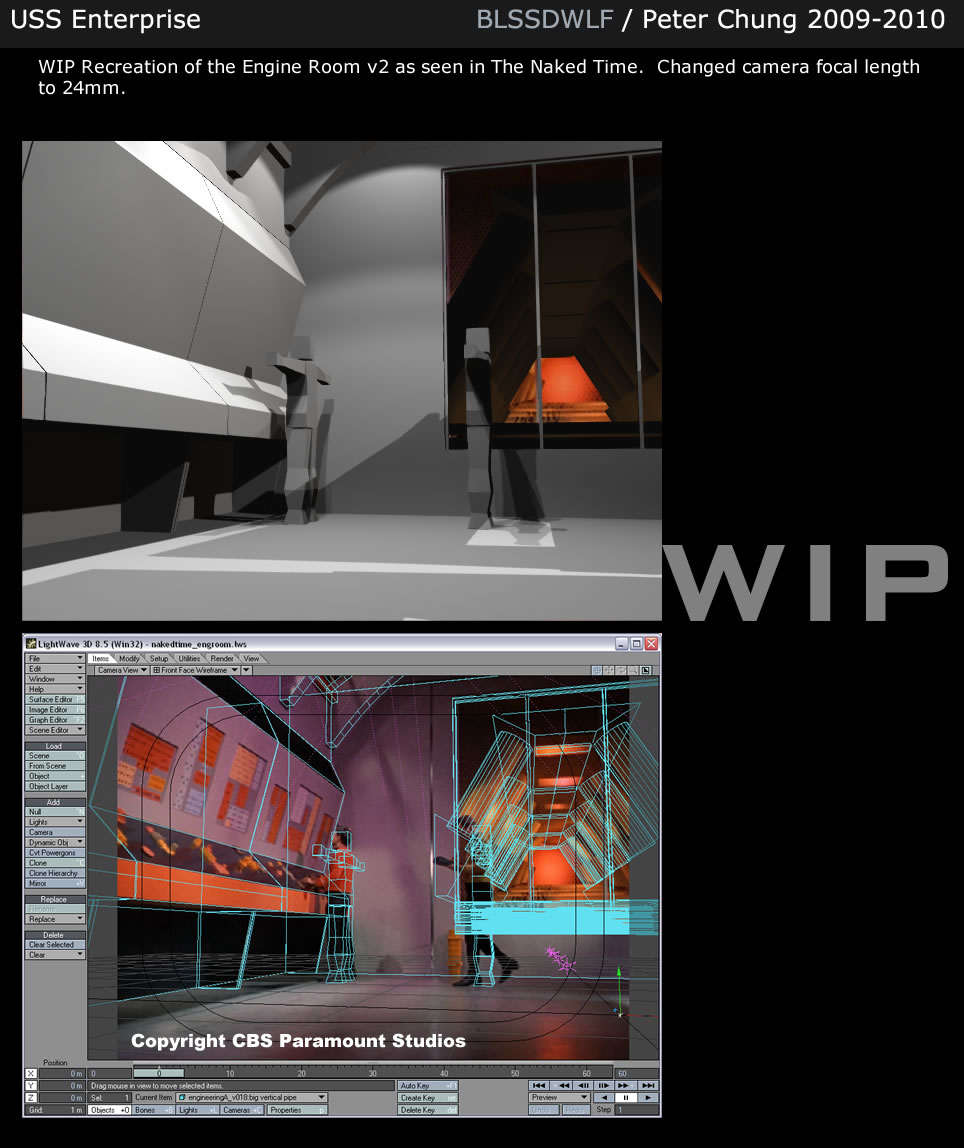
But I'm really getting tempted to turn that pipe structure into the force-perspective prop as shown in the episodes
Similar threads
- Replies
- 482
- Views
- 59K
- Replies
- 10
- Views
- 3K
- Replies
- 87
- Views
- 20K
If you are not already a member then please register an account and join in the discussion!