Another take on the Original Enterprise...

Discussion in 'Fan Art' started by Cary L. Brown, Apr 24, 2009.

Thread Status:
Not open for further replies.
  1. Cary L. Brown

    Cary L. Brown Rear Admiral Rear Admiral

    Joined:
    Oct 14, 2005
    Location:
    Austin, Texas
    Well, that's an interesting suggestion. I don't see a problem with doing exterior hull shapes that way, though I'd be disinclined to have the actual "core structure" assembled in the same way, considering just how much stress the secondary hull really has to carry during extreme manuevers.

    David's take, which I like, is that the primary hull is subdivided into "pressure compartments." I'm not sure if he's talking about building separate sections in different locations and strapping them all together, though. I get the impression he's thinking more in terms of how contemporary shipbuilding is done... where if you "hull" a portion of the ship, the other portions retain their environmental (and structural) integrity. If you build it as I think you're suggesting, I think you'd be compromising the overall strength of the structure.

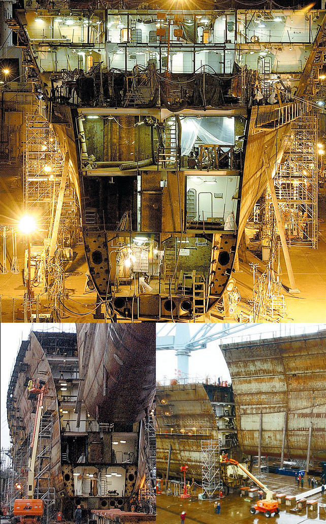
    A better model might be to look at a large ocean-going vessel. There are individual compartments, with watertight doors, throughout the ship. But there are also ... I can't recall the correct term here, so I hope someone else will chime in... but certain walls which are VERY heavy, reinforced, typically double-walled and double-hatched. The idea is that if one section of the ship is damaged, and even floods entirely, the remainder of the ship can still function.

    I know that David is working from the "Pressure compartments" diagram. I don't believe that he's assuming that each pressure compartment was built in a different location and then "bolted together." And I'm certainly not presuming that, in any case, though I do like the idea of certain "watertight" sections of the ship being effectively independent from others.

    (David, want to chime in on this? I don't want to misstate your position.)

    As I see it, each of those regions can be sealed off and has its own local life-support system, which can't be lost if adjacent pressure compartment is compromised. (Again, this is one of my gripes with the nuEnterprise... particularly in the engineering section, but generally throughout the ship as we've seen it so far. There's no sign of "compartmentalization," whereas the TOS ship had clear indications of that (the trapezoidal "section doorways" you'd see in certain places, I always assumed were locations for section-isolation hatches).

    I do like the idea of the hull being assembled in subelements, then those being assembled into the complete structure later. That's very much a parallel to how real vessels... particularly aircraft... are manufactured.

    For instance, look at a large jetliner. While the midbody (including the primary wing spars) is not constructured in that sort of fashion, the remainder of the (lower-load-bearing) fuselage segments are built in exactly the manner you describe. For example, see this:

    [​IMG]

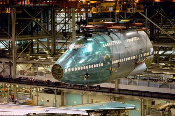
    So I have no problem with that sort of construction technique being used. I'm a lot less sanguine about it being used for primary load-bearing elements, and I'm certainly not in favor if it being a "bolt-together-like-tinkertoys" approach, unless that's in a region that has no real load-bearing capability whatsoever.

    There are several regions on the ship which meet that definition quite well, by the way. The actual hangar-deck portion of the ship carries no load other than that created by its own mass. Similarly, the uppermost and lowermost portions of the primary hull should be easily swapped out (and is, in fact, the reason I've adopted for the "concentric rings" on the underside primary hull). And since the deflector sees similarly low loading (except for pure-compressive loads which would be transferred, in my approach, directly into the secondary hull "keel" structure) it could be swapped out very easily as well.

    What does this mean re: your suggestion? Basically... that the secondary hull "keel" and "strongback" elements cannot be compromised, and once the secondary hull "shell" elements were assembled, it would be a massive undertaking to strip them out (effectively requiring them to be ripped out wholesale). Just like you can't simply pop out a segment of a 747 once integrated.

    That's my take...
     
  2. Shaw

    Shaw Commodore Commodore

    Joined:
    Feb 21, 2007
    Location:
    Twin Cities
    The assembly by parts follows the same idea that you illustrated with the 747 assembly and I used this similar set of images of the construction of the Bush...

    [​IMG]

    But once assembled and integrated into the ship's structure there are key elements that can not be taken apart without significantly compromising the integrity of the ship itself. This is the same type of thing that happens with our carriers when being overhauled... to remove the engines it is better to cut through a number of decks, the hangar and the flight deck than to compromise the hull itself by cutting through it.

    In that way, while I see some of the areas of the primary hull as replaceable (the outer most ring and upper and lower elements), with the secondary hull I see only a few removable elements within and all of them having to be extracted via the flight deck doors (by cutting through the back wall of the flight deck) so as not to compromise the structure of the outer hull.

    The main reason for having the compartment boundaries associated with the assembly of the hull sections in my case is so that internal operations can get started during assembly. This isn't an issue for naval ships (as seen above) because they don't have to worry about maintaining an internal atmosphere during construction.

    ______________​


    As a side note, I'd point out to everyone the water and fuel storage areas beside and below the lowest deck of the carrier images above. That area is analogous to what Cary described here:
    "The combination of the "strongback" and the "keel" is what gives the secondary hull it's mechanical strength. The "strongback" will essentially be subdivided into a series of very small compartments... which makes it perfect for fluid or bulk-particulate material storage (containers being strung between the structural members, not actually being made up OF the structural members)."
    This is the type of well thought out engineering that makes this a great project to follow. :techman:
     
  3. Icy_Penguigo

    Icy_Penguigo Captain Captain

    Joined:
    Feb 28, 2007
    Location:
    Tacoma, WA, USA
    Cary: I haven't spoken up so far in this thread....but I have been following it religiously. I just wanted to say, this has been one of the single most fascinating Star Trek art projects I've ever had the pleasure to witness. You, and many others in this thread, have had extremely interesting and thoughtful insights, and I sincerely hope you can find the time and will to carry it to completion. The Enterprise has never been so real! Hats off to you, sir. Thank you for sharing this amazing work with us so far.
     
  4. Psion

    Psion Rear Admiral Rear Admiral

    Joined:
    Oct 19, 2001
    Location:
    Lat: 40.1630936 Lon: -75.1183777
    Shaw, I love those images of the Bush. Do you have any more you could share with us or post a link to your source?


    Hmmm ... it almost sounds like I'm asking for porn.
     
  5. Shaw

    Shaw Commodore Commodore

    Joined:
    Feb 21, 2007
    Location:
    Twin Cities
    My collection came from a number of sources, but the majority of images (and majority of the best images) came from this article:In Chapter 6 there is a diagram of the pieces that were prefabricated and assembled.

    I don't know if carriers are the best comparative vehicles to starships, but I know I have a sentimental attachment to them (this was less than a mile from my high school)... specially to the Kitty Hawk and Constellation.
     
  6. Cary L. Brown

    Cary L. Brown Rear Admiral Rear Admiral

    Joined:
    Oct 14, 2005
    Location:
    Austin, Texas
    Well, the parallels are (at least to my mind) far closer than the differences.

    The reason that you build things this way, instead of "building it all at once," is just a simple matter of scale. It's damned difficult to build an unsupported frame all at once. Construction in "slices" or "chunks" allows you to get all the details right in one area, with a much more narrow focus, than you might have otherwise.

    The challenge is in ensuring that the various segments are, in fact, able to be integrated... which means that the various points where they'll be joined must be held to pretty close tolerances. The size of the "chunks" ultimately comes down to "how much ability to flex, during integration, do you need?

    The same basic requirement drives the use of this in shipbuilding and in aerospace, by the way - that is, the desirability of being able to break a massive assembly down into manageable, bite-sized pieces.

    Granted, I'm sure that in the future, there will be new technologies which are either improvements upon, or entirely new concepts we've yet to really envision, for manufacturing. But regardless of the tools being used, the idea of breaking a big thing down into more manageable smaller things is, I think, always going to be advantageous.

    A starship is a very big thing. :)
     
  7. Praetor

    Praetor Vice Admiral Admiral

    Joined:
    Apr 18, 2004
    Location:
    The fine line between continuity and fanwank.
    Thanks for those links, Shaw! What awesome high school lunch periods you must've had. ;)

    I just learned that there's a group here in North Carolina that wants to get the Kitty Hawk after she's decommissioned to add to the U.S.S. North Carolina museum in Wilmington. In would cost mucho dinero to move it and dredge it out a berth and all (and it won't happen til after 2015) but it would be awesome.

    Regarding the modular dilemma - why not build the ship in modules in smaller hangars on Earth, assemble those sub-assemblies into the basic hull components, then assemble the whole thing in orbit? Shouldn't that take care of integration issues?
     
  8. Cary L. Brown

    Cary L. Brown Rear Admiral Rear Admiral

    Joined:
    Oct 14, 2005
    Location:
    Austin, Texas
    That is, of course, essentially what was described by the TOS production staff (a fair number of whom were prior-military-service types, and I'm sure that at least a few were very familiar with naval construction techniques)... ie, that the Enterprise was built as components on Earth and then assembled in orbit.

    The general assumption has always broken it down by "saucer, cigar, nacelles" as being the components which were built on Earth, but there's no practical reason it couldn't be as we're discussing.
     
  9. Psion

    Psion Rear Admiral Rear Admiral

    Joined:
    Oct 19, 2001
    Location:
    Lat: 40.1630936 Lon: -75.1183777
    Thank you, Shaw. This sort of material is not only fascinating on a personal level, but helpful for a side-project I'm working on involving a wet-navy ship.

    And I'd also argue that carriers are a fine comparison for starships like the Enterprise. The original series never seemed very distant from them. The hero ship was named after one of the most famous carriers of World War II and the first nuclear-powered aircraft carrier. Her sister-ships bore carrier names, and the size was often compared to a carrier. So, fictionally -- not from a real world engineering standpoint, but metaphorically or from a story-telling perspective -- the Enterprise should be built like a carrier.

    I'd take it further. You know that grid everyone since Franz Joseph calls the "deflector grid" on the primary hull? I think those are the construction seams. The saucer was assembled from pie slices and the secondary hull went together as cylindrical slices.
     
  10. sojourner

    sojourner Admiral In Memoriam

    Joined:
    Sep 4, 2008
    Location:
    Just around the bend.
    Well, not even modern ships have construction marks left over that are that noticable. Here are some picks from the time I spent working on final outfitting of the Navigator of the Seas cruise ship. The first 4 pics are of the Mariner of the Seas being assembled just in front of the Navigator. If they wanted to they could have pumped these out at the rate of one per year. As it is Royal Caribbean only paid for 5 of this class. I served as a Systems Manager aboard Navigator for 2 years after completion. The last pic is the server room under construction. My desk is on the left, hehe. Probably the closest I will come to serving aboard a federation ship.;)
    (click on images for full size)
    [​IMG]
    [​IMG]
    [​IMG]
    [​IMG]
    [​IMG]
    [​IMG]
    Sorry if this has hijacked the thread too much, but I have been dying for an excuse to post these.:)
     
    Last edited: May 19, 2009
  11. Cary L. Brown

    Cary L. Brown Rear Admiral Rear Admiral

    Joined:
    Oct 14, 2005
    Location:
    Austin, Texas
    FYI, I don't consider this "hijacking" at all, since it's really on-topic... the thread being focused on demonstrating the most "real" version of Enterprise I can come up with (only using "magic generators" when there are glaring holes in our knowledge of real science).

    The "how would the ship be constructed" idea is, really, fairly central to the thread topic.

    In my case, I assume that the main "keel" structure (secondary hull "core," dorsal, pylons, and aftmost "wedge" of the primary hull) will be constructed independently, as one structure. From there, modular construction of the sort we're talking about would take over.

    For the primary hull, we'd see a central core, and (as mentioned above) a series of "pie wedges." I'm not sure that the lines on the hull are necessarily "weld lines," though I don't object to that idea, either (it really depends on whether or not you treat the primary hull surface as painted or unpainted, I think... since I'm sure that the welds would be so fine as to visually imperceptible unless you were right on top of them if you were relying on "weld bump/groove" detection!)

    I envision the primary hull "wedges" being a series of flat structural sections forming radial ribs. The "flats" would be most easily built on a large planar surface in a gravity well, of course (preferably at the San Francisco Naval Yards). And, given an appropriate "cradle," I can see the wedges assembled on the ground as well. This "common structural elements" theme is part of what I actually really liked about F.J's design strategy... one production facility able to support, without reconfiguration, components for a variety of spaceframes.

    Now, for the secondary hull... I do envision a series of flat "rings" constructed (and partially internally populated) which are then strung over the keel and joined to both.

    The dorsal deck structure would be considered part of the keel, so that would be in the primary construction stage, however.

    As for nacelles... well, that's sort of tricky. It's nice to consider the idea of "hot-swappable" nacelles, but I'm not convinced that's the best idea, given the attachment method. If we DO use that general concept, the pylon "beam structure" definitely needs to extend all the way through the nacelle body, through a "receiver" in the nacelle structure at that location. In other words... it's not just "unbolt and remove". Rather, you have to do significant disassembly to the nacelle in the attachment region. (I tend to lean towards the big red rectangle on the nacelle underside as being a "cut on the dotted line" indicator for this purpose. ;) )
     
  12. sojourner

    sojourner Admiral In Memoriam

    Joined:
    Sep 4, 2008
    Location:
    Just around the bend.
    Yea, I tried to do a "plating mounted to structure" on the Capella model I am building. Unfortunately it doesn't show up at all unless really close in and thats with 1/2' thick plates with a 1" gap between them! In fact, I will probably go back and redo the "deflector grid" as a raised half circle crossection and ditch the plates.

    [​IMG]
     
  13. Cary L. Brown

    Cary L. Brown Rear Admiral Rear Admiral

    Joined:
    Oct 14, 2005
    Location:
    Austin, Texas
    Very interesting...

    The ultimate question is... "what are those lines." I do like the idea that F.J. came up with, but not in the way it's often been portrayed.

    The thing to think about when you see that sort of line is "wave guides." I see these features as channels, part of the hull, whose purpose is to help the energy of the "skin field."

    Let me explain for anyone not familiar with what I'm talking about. The Enterprise, in TOS, and most explicitly described in TMP, had two defense systems... a "second skin" forcefield, and a distant-from-the-hull, gravity-based "deflector." Deflectors and shields were not really the same thing. When you see the TNG-era "ovoid"... that's equivalent to what I'm calling the deflector screen.

    How does this work?

    Well, you have this deflector screen (remember, we often hear about raising "screens and shields") which basically serves to dissipate and, yes, deflect, incoming weaponry. Instead of an intense beam of energy hitting one spot on the hull, you get a refracted beam which may miss entirely, or may spread some portion of its energy across a wide region of hull rather than a single spot (almost certainly with some portion missing entirely in any case). For projectile weapons, a torpedo would effectively be pushed off-course as it hit the screen, which would usually be sufficient to cause it to miss.

    Anything which is not deflected by this system, and which impinges on the hull, doesn't hit the physical hull, however... instead, it hits the shield... aka the "forcefield"... essentially the energy-based second-skin. It inflicts damage on that, rather than on the physical hull. Only if it completely overpowers that system and penetrates it does the hull see an impact... in which case, of course, the hull is pretty tough as well, and has self-sealing properties for small punctures. I assume a pocketed/compartmentalized layer of two fluids, separated by a barrier, which when penetrated (and allowed to come into contact) forms a fast-curing (and able to cure in vacuum) expanding foam. Think "Great Stuff" plumbers foam, but taken to an extreme, basically.

    (Side note.. the "foam to seal hull leaks" concept isn't original to me. The first time I ever saw this done was on Blake's Seven... one of the best shows ever, and one deserving of a good revisitation, though I suspect the recent attempt to revisit it will end up like most "reboots" go... it'll miss the good stuff and keep the stuff we could afford to lose, in other words.)

    Anyway... back to the "gridwork." ;)

    I see that gridwork as being a series of waveguide "channels" in the hull, which serve to help that "skin field" flow more effectively over the hull, evening out areas which (without that grid) might see insufficient coverage. Basically, the "shield grid" (not "deflector grid") doesn't actually generate the shield, it ensures that the shield doesn't have weak spots.

    Because of this approach, well... I figure that the size of the channels would scale with the size of the vessel (it makes sense... if you assume several centralized generators have to "flow" the shield across wide areas. The bigger the "rivers" you have for that flow, the faster the "water" of the shields flows through them.

    In my (oft-referenced) Vega, I used pretty huge channels... 0.25m diameter circular cuts into the hull surface. For a smaller ship, I'd use smaller grooves. Since this thread isn't about the Vega class, I won't post the full-size image, but here's a thumbnail, which you can click (a couple of times... damned ImageShack... ;) ) to see the full-size image. I think this works quite nicely, personally...
    [​IMG]

    Now, re: the Enterprise... I don't plan on implementing anything like that. I could never see the gridlines on my set. They were basically light pencil lines, and I think it's pretty evident that they were never intended to be seen on-screen. Rather, I think that they were "construction lines" for helping to lay down lettering and so forth... placing details which COULD be seen on-screen. (Anyone who's done old-style manual drafting knows what I'm talking about when I discuss "construction lines"... but for those who don't, they're basically features which are drawn, only to be erased later, which help you line things up properly in a manner other than "just eyeballing it.")
     
  14. USS Mariner

    USS Mariner Rear Admiral Rear Admiral

    Joined:
    Jul 11, 2004
    Location:
    Homestate of Matt Jefferies
    FYI, you can easily link the images directly to the thumbnail, with no middleman screen in between.
     
  15. CTM

    CTM Lieutenant Commander Red Shirt

    Joined:
    Apr 15, 2009
    Location:
    The exact center of my universe
    What about a Whipple Shield? I see it as likely a fairly standard practice. The pressure hull is offset some distance inside the visible hull (doesn't have to be much) allowing high-speed particles to impact the shield and expend most of their energy against the outside, and spreading out the energy over a larger area inside the shield. If something gets through the deflectors, shields, screens, and all the other semi-fictional defensive systems, the last barrier before reaching the vital pressure hull would be the Whipple Shield.

    A good photo of a Whipple Shield is here: http://hitf.jsc.nasa.gov/hitfpub/shielddev/whippleshield.html
    You can see the impact test on the right panel, and the vaporized residue that did not penetrate the inner hull on the left. Separation is only a few inches.
     
  16. Firebird

    Firebird Commodore Commodore

    Joined:
    Apr 23, 2005
    Location:
    On the Cinerama screen, in glorious Technicolor.
    Cary, I've gotta echo some of the sentiments expressed thus far. You are doing FANTASTIC work on this project! It's great to see a more "realistic" technical approach to building the Enterprise. I can't wait to see how your, and Shaw's interpretations of the Big-E turn out.
     
  17. Cary L. Brown

    Cary L. Brown Rear Admiral Rear Admiral

    Joined:
    Oct 14, 2005
    Location:
    Austin, Texas
    I've never heard the term "whipple" before, but the concept of laminated armor (dissipating energy at layer boundaries) is certainly a well-known, and very effective, concept. Where does the term "whipple" come from, if you don't mind my asking?

    There are really two forms of armor... the "impenetrable, super-hard, super-tough, super-dense" type, and the "dissipation of energy" type. Interestingly, the first is generally less effective than the second... because there's no such thing as "impenetrable." ;)

    Probably the most effective tank-killer weapons are generally what are called "Sabot" rounds. They fire as though they were a normal shell,then discard the "sabot" (an outer shell), transferring virtually all of the energy into a single, hypervelocity carbide needle. When it impacts an old-fashioned armor plate, it simply liquefies that plate. The term "hot knife through butter" really applies very well.

    I remember seeing a sabot round test once... with a live (animal) test subject inside the target vehicle. Inspecting the vehicle after the impact, you found a smallish hole at the impact point... a slightly larger "exit wound"... and literally NOTHING remaining inside the hulk. There was no evidence that the animal had ever been in there... totally vaporized and "sucked out" the "exit wound" on the vehicle.

    How do you defeat something like that? Well, two methods are typically used... ideally, in combination. First... laminar armor, where the outer layer accepts the majority of the energy-transfer, and the inner layer protects from the outer layer. But this isn't sufficient most of the time. So, they use something called "reactive armor." What this is... is actually a layer of explosive strapped to the exterior of the tank, over the armor. Sounds crazy, on the surface, huh? Except... the explosive charge "defocuses" the energy of the projectile, and can prevent it from penetrating the vehicle. It's remarkably effective.

    Your suggestion... what you're calling "whipple" armor... is, I think, a required element of ANY starship hull construction. Even if you're not concerned about going into combat, space is so filled with hazards that it would be almost insane NOT to use that sort of construction.

    I believe, by the way, that Sternbach and Okuda had something similar in mind (not sure, since it's so technibabblish, if their solution would actually WORK, but I know that's part of what they were steering for) when they described the multi-layer hull construction of the 1701-D in the TNG Tech Manual.

    In my case... my hull thickness is a nice, uniform 0.357 meters (actually, it's a bit above that, but I think three places is sufficient for this conversation!) That's approximately 26". Since my structure is really more based upon internal structure than any "monocoque" form of construction (as modern airliners tend to be, carrying most of their strength in the skin and associated "stringers"), realize that most of this is for exactly that sort of purpose... the "skin" of the ship is there to protect the stuff inside, not to provide the shape or the strength of the ship. I could easily have gone with a much thinner skin, as a result, except that yeah, I was thinking along the same lines you are. :)
     
  18. FalTorPan

    FalTorPan Vice Admiral Admiral

    Joined:
    Jan 25, 2000
    Location:
    Out there... thataway.
    This has been a fascinating thread, but I'm in number-crunching mode, and I couldn't help but notice that 0.357 meters is about 14.1 inches. 26 inches works out to about 0.66 meters.
     
  19. CTM

    CTM Lieutenant Commander Red Shirt

    Joined:
    Apr 15, 2009
    Location:
    The exact center of my universe
    Fred Lawrence Whipple. His "Meteor Bumper" or more formally "Whipple Shield" is explained here: http://en.wikipedia.org/wiki/Whipple_shield Be sure to follow the off-wiki links to NASA's demos of the Whipple Shield pen-tests.
     
  20. Psion

    Psion Rear Admiral Rear Admiral

    Joined:
    Oct 19, 2001
    Location:
    Lat: 40.1630936 Lon: -75.1183777
    Absolutely no offense is intended, Sojourner, but those pictures are a bit muddy and have a subject very evenly lit. A lot of detail gets washed out in those conditions. If you check out the Bush construction photos provided in Shaw's link, you can see the seams very clearly even on the painted hull. Of course, your point isn't lost. At a distance, you can't make out the seams, and that's my point about the original Starship Enterprise: no one saw the penciled-in seams (although somehow FJ did and exaggerated them for his drawings). So it was an extremely fine seam left as each pie section was joined to its neighbors. "Gamma-welded" doncha know?

    I'm not sure I buy Cary's theory about waveguides, but it does provide an explanation for the change in texture of the vessel by the time The Motion Picture roles around. We go from practically invisible grid markings to deep insets. Sulu remarks after the first whiplash bolt from V'Ger hits and dissolves, "The new screens held!" Maybe there's something to these new details being part of the defensive system upgrades. We see a similar change in texture on the Klingon ships, too. Maybe the screens were uneven, new technology when NCC-1701 was built and waveguides improved their reliability.

    And here's some background on Mr. Whipple. No, not the Charmin guy! :rolleyes:

    EDIT: Ah ... I see CTM has beaten me to the last point.
     
    Last edited: May 20, 2009
Thread Status:
Not open for further replies.