Another fan attempt at TOS deck plans

Discussion in 'Fan Art' started by Shaw, Feb 11, 2008.

Thread Status:
Not open for further replies.
  1. FalTorPan

    FalTorPan Vice Admiral Admiral

    Joined:
    Jan 25, 2000
    Location:
    Out there... thataway.
    I think it's almost pointless to discuss the structural framework of the TOS ship, since the ship's overall geometry -- though visually appealing -- defies common sense when it comes to a sound structural design. Ask almost anyone who's built a model kit of the thing. :p
     
  2. Bill Morris

    Bill Morris Commodore Commodore

    Joined:
    Apr 10, 2005
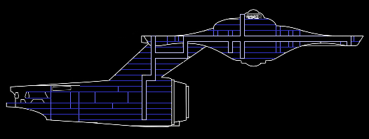
    Maybe this is a dumb question, but why wouldn't the layout be more regular, to maximize use of standard components and simplify the design of the turboshaft system? Here, I've tried to even out the deck heights while more or less agreeing with the rest of what you guys are saying.

    [​IMG]
     
  3. Shaw

    Shaw Commodore Commodore

    Joined:
    Feb 21, 2007
    Location:
    Twin Cities
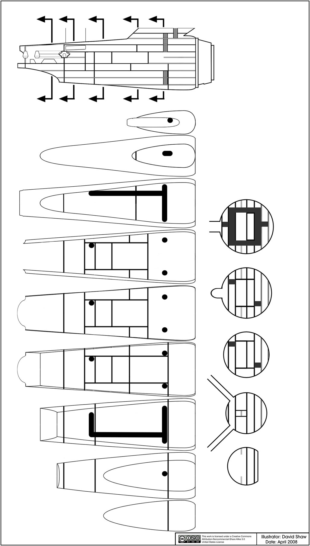
    The deck heights are derived from a number of sources... most are an attempt to do everything at about a 10 foot ceiling height, but others are working from approximately Jefferies heights shown in his Phase II plans, while the heights in the dorsal are a direct result of the window placement on the 11 foot model.

    The turbolift shaft placement is based on a topological study of the inside of the Enterprise (which shouldn't be surprising as my area of expertise in mathematics is differential topology) taking shaft placement, corridor placement and compartment placement into account.

    It is sort of like a cooperative game of Tron motorcycles. In this game the goal is for neither the shaft cycle nor the corridor cycle to cut each other off. The shaft cycle also has the ability to easily jump from one deck to another while the corridor cycle is limited to staying on any given deck.

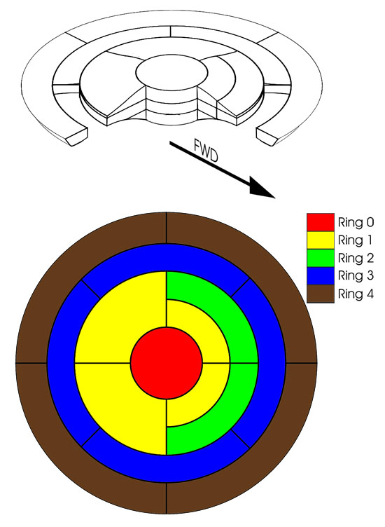
    Also, the layout makes an attempt to not bisect any compartment. In the layout you have shown the shaft cuts at least one compartment in ring 3 on deck 5 completely in half. Compartments in ring 3 are (for the most part) a single deck thick, so if that compartment was to be isolated, the two halves would also be isolated from each other too. Every compartment is a life boat, and in the case of an emergency, everyone within a compartment would be interdependent... but if their compartment were bisected, you would have two groups cut off from each other.

    Additionally, walking is good for you. And the outer rings are the enlisted cabins, and they can use a little exercise. :D

    Edit: Oh... and sickbay takes up most of ring 0 on deck five, and in your diagram the shaft would basically cut sickbay in half too (though the compartment as a whole would be fine).

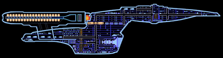
    This image is from quite a while back, but I think it is helpful in envisioning the compartment layout in the primary hull

    [​IMG]

    Another issue to keep in mind is how to maximize the ability of traffic to flow within the turbolift network itself. The best way to do this without eating up more of the ship's internal volume is by assigning traffic rules. The primary hull has one loop with a number of branches, while the secondary hull has two loops with a number of stop points where the turbolifts can pull off. All loops are one way (you start down a loop, you have to go the same direction until you get off on a branch), while branches are two way, where empty turbolifts have to yield right of way to full turbolifts, and turbolifts arriving at their destination have right of way over turbolifts just departing (which is also somewhat dependent on the destination not being occupied). As all turbolifts have 6 activation handles, any turbolift without all 6 handles activated has to stop at any turbolift station on a branch while leaving that branch to pick up more people. More turbolifts can be added to the system in high traffic periods, with the extra in a holding pattern in one of the loops until they are needed. This setup should make sure that a turbolift can be at a station within 15 seconds of someone waiting to get on.

    While most of this can be automated, I assume that their is at least one person on duty at all times to direct traffic as needed. Kirk yelled at Uhura to clear the shaft going to the bridge once, which means she most likely had to call that person to direct a turbo lift to the bridge for the captain.


    :wtf: Okay, that might have been more information than you wanted, but at least it sort of covers what I was thinking at each point in the process.
     
    Last edited: Apr 20, 2008
  4. Bill Morris

    Bill Morris Commodore Commodore

    Joined:
    Apr 10, 2005
    Well, a turboshaft layout as represented in any MSD can be misleading, since it looks two-dimensional. I saved a copy of your wireframe turboshaft diagram. That seems to make sense. I have to pay attention to rings. For starters, I'll shorten the forward shaft shown in the study drawing I posted and take your advice about the rest of the turboshaft layout as it should appear in an MSD.

    About the deck heights, yes, I've looked at the drawings by aridas sofia and Captain Robert April, too. I agree pretty much about number of decks. One beautiful cutaway by Jonathan Burke shows the decks evenly spaced but disagrees with you guys on number of decks and many other things.

    But every canon MSD I'm familiar with has the decks evenly spaced, even though the windows on the filming models or CGIs seem to disagree in many cases. But maybe the windows are just higher or lower in relation to the floor on some decks than on most others (which is true for some real-world buildings). And some decks seem to have two rows of windows. Then there's the Diafiant, with three rows of windows on each inner side of deck four.

    Anyway, if I can make peace with the deck layout I'll draw up an MSD of this ship and include it in the next release of my LCARS system, in the style of the Ent-C, shown below, and make it agree as much as possible with what you guys are thinking.

    But I'm still not convinced that the TOS Enterprise would have so many slight variations in deck height as I have seen here so far. Some are 11 feet, some 10, some 9. It's possible, I suppose, but wouldn't that have added a few billion to the construction cost? Or I could take the attitude that an MSD is like a subway map, oversimplifying things, and not worry about any possible design quirks in the original.

    [​IMG]
     
    Last edited: Apr 20, 2008
  5. Shaw

    Shaw Commodore Commodore

    Joined:
    Feb 21, 2007
    Location:
    Twin Cities
    Well. I'm not too worried about canonical stuff as (quite frankly) I'm not even sure what falls into those categories. I also don't know that much about MSDs and haven't familiarized myself with their conventions as they weren't part of TOS. So in my plans a cross section is generally a pretty strict cut down the center line and often doesn't show much beyond that (though with the lack of major internal arrangement of the secondary hull, I have been showing the turbolift shafts completely even though major parts fall either deep within one side or would have been cut off with the other side.

    Here are two unfinished sheets from my notebook, one includes a general cross section with many of the current elements and the other is a better view of the 3D turbolift network.


    The main object here is to try to fit the interior within the exterior with as little (or no) alteration as possible. While some of the stuff was undoubtedly rushed (like the deck heights in some areas), the primary goal is to show that a lot more thought went into this than most people generally assume.

    In fact, when looking at the TOS Enterprise, it is vastly less self-contradicting than some of the later Trek ships like the Defiant from DS9. I was amazed to find that that vessel was hardly thought out at all even though most of the people working on the show at the time are former techie fans like us and should have known that we would have wanted a certain level of internal consistency.

    Now, in all fairness Jefferies had between 1964 to 1966 to work out the logic of the interior of the TOS Enterprise (which is far longer than I've spent on this project and he was getting paid for his work too). So by the time TOS started filming, I'm sure that Jefferies had concepts about the workings of the Enterprise as complete as anything I've put forward in this thread. What he didn't do (which I also haven't yet done) was put all of that information together into a self-contained set of plans. But had he done that, he would not have used the 11 foot model as his exterior, he would have most likely used his original construction plans as a basis (which was what I had originally intended to do as well).

    But yeah, I'm quite sure that I could improve on tons of stuff, but in this case I'm trying to let as much of Jefferies vision show through as possible. In areas where he left a lot open to interpretation (the corridors and turbolift shafts) I've applied my expertise in organizing the best solution that maximizes the overall efficiency of all related areas. The best turbolift layout might have catastrophic effects on other aspects of the ship, systems analysis takes the workings of all the systems to an efficiency equilibrium point. So while if you look at any one system by itself, you would see that there might be a better way, the better way for that system isn't always the best way for the ship as a whole.

    I would point out that where I seem slavish to Jefferies' stuff or the 11 foot model, those are more or less self imposed restrictions... I'm in no way suggesting that this is the Enterprise and all other interpretations are by consequence wrong. The Enterprise is a work of fiction which exists uniquely in each of our hearts and minds. I'm actually looking forward to people applying their own ideas of this stuff eventually, and basically throwing out my ideas and putting in their own to see how things might fit together. That is one of the reasons why I wanted to have scaled set plans, but not have them directly linked with a 947 foot long design... some people don't agree on that length, and I don't want to hinder their ideas.
     
  6. Bill Morris

    Bill Morris Commodore Commodore

    Joined:
    Apr 10, 2005
    Okay, the top one is something I'm seeing for the first time. There is obviously some logic to what you've done with the tuboshafts there, and maybe the shape demands that even the decks within the saucer not all be the same height. And the rest, as you mentioned, does seem consistent with the windows.

    I saved a copy of that, and maybe I will follow that structure and put your name in the credits, if that's okay with you.
     
  7. Shaw

    Shaw Commodore Commodore

    Joined:
    Feb 21, 2007
    Location:
    Twin Cities
    That would be great!

    There is a lot of this stuff that I have sketched out as pencil and paper drawings, or has been eluded to in this thread but all the pieces haven't quite been put together yet that I'm hoping to make much clearer within the notebook.

    Hopefully I'll be able to get caught up on my work soon and can devote a little more time to this in the near future.
     
  8. Bill Morris

    Bill Morris Commodore Commodore

    Joined:
    Apr 10, 2005
    Good. I've been following this thread, and I'll keep an eye out for updates.
     
  9. Cary L. Brown

    Cary L. Brown Rear Admiral Rear Admiral

    Joined:
    Oct 14, 2005
    Location:
    Austin, Texas
    I'm happy to see that the "thinking in 3D" method of turbolift design is becoming more popular! ;)

    It's really challenging when you lay out entire decks to come up with a lift system that doesn't (as David stated) bisect entire areas. Basically, you NEED to have the ability to walk/climb from any part of the ship to any other part without having to pass through the lift system at any time. And you really want the walkable portions to be the more direct, even if it means that the lift portion has to go a bit out of it's way.

    It's always worth remembering that, ideally, you WANT the crew to walk rather than ride the lifts. It's a health/fitness thing. The lifts are there for carrying heavy equipment, for "I'm running late and have to be there NOW" purposes, and for "it's a red alert and I need to get to the bridge or we all die!" purposes. But they should NOT be the preferred method of transit.

    No starfleet ship... not even the Galaxy.. is big enough to justify never walking to your job. I walked twice as far as the length of the Galaxy primary hull from the car dealership to my place of work, and back, several days last week (getting my A/C system refurbished after the condenser coil failed) and it was NOTHING. Had it been raining, I might've waited for the shuttle service, but c'mon... it's GOOD FOR YOU! Especially if you have a job that involves sitting at a desk (or bridge console) all day!

    Of course, some officers take the lift everyplace... I'm sure that's what was behind Scotty's weight gains. ;)
     
  10. MGagen

    MGagen Fleet Captain Fleet Captain

    Joined:
    Feb 28, 2003
    Location:
    Crucis Court, Trans-Coal Sack Sector
    Thanks, Aridas.

    I'd like to clarify this a bit: The Polar Lights decal placement guide, while quite small, is the most accurate of the publicly available plans.

    The main reason for this is that they are based on Gary Kerr's excellent work ...

    M
     
  11. Warped9

    Warped9 Admiral Admiral

    Joined:
    Aug 3, 2003
    Location:
    Brockville, Ontario, Canada
    I would love to be able to see this work.
     
  12. Captain Robert April

    Captain Robert April Vice Admiral Admiral

    I think it might be a bit of a public service, then, to point out the deliberate errors that Mr. Sasser put in that decal placement guide, for the express purpose of hamstringing efforts like this one, so that the appropriate corrections can be made.
     
  13. Shaw

    Shaw Commodore Commodore

    Joined:
    Feb 21, 2007
    Location:
    Twin Cities
    So I don't want you guys to think I forgot this stuff... I've just been really busy with a ton of other things lately.

    I have been thinking about how to brake up the secondary hull into unique compartments and what might go into which compartment. This sort of gives an idea of where I'm at right now.


    I've included a number of slices across the hull to illustrate how the compartments (and decks) are arranged within the hull (specially as in some areas there are open areas that are more than a standard deck high).

    Engineering is basically the core of the hull, with sections on either side (just towards the aft) that would serve as storage areas (and are associated with parts of the hull with few windows). Engineering also includes the compartment that meets with the nacelle supports (which I envision as where Scotty was working in a Jefferies Tube in That Which Survives).

    It is funny, if most of the engineering areas were relocated to their TMP locations, then the vacated areas would make up the large open areas seen in the refit Enterprise. And the turbolift tubes as I have them currently aren't too far off either (about 15 meters or so forward of the ones seen in TMP I'm guessing). Even though this is all coincidence, it is still interesting that those aspects even remotely match up at all. :eek:
     
  14. Warped9

    Warped9 Admiral Admiral

    Joined:
    Aug 3, 2003
    Location:
    Brockville, Ontario, Canada
    Shaw, this is just wicked stuff!. First CRA, then aridas and now you. :techman:
     
  15. Firebird

    Firebird Commodore Commodore

    Joined:
    Apr 23, 2005
    Location:
    On the Cinerama screen, in glorious Technicolor.
    I can't wait to see all of these blueprint sets completed!

    I always love your stuff, Shaw! You put a ton of thought and effort into it that puts anything I would ever draw to shame.
     
  16. Praetor

    Praetor Vice Admiral Admiral

    Joined:
    Apr 18, 2004
    Location:
    The fine line between continuity and fanwank.
    Me likey the secondary hull concepts a lot! They make a lot of sense and gel with notions that I've always held true. I can't wait for more!!!
     
  17. TIN_MAN

    TIN_MAN Fleet Captain Fleet Captain

    Joined:
    Aug 26, 2007
    About those turbo lift shafts, It's always been my understanding that the exposed shafts in ST:TMP represented 'artifacts' from the refitting? In other words, the shafts were in the same place they always were, but the bulkheads and what not had been moved around or removed altogether, so your right on track it seems!:techman:
     
  18. FalTorPan

    FalTorPan Vice Admiral Admiral

    Joined:
    Jan 25, 2000
    Location:
    Out there... thataway.
    That's an interesting assumption. Of course, we have no way of knowing if that "really" happened.
     
  19. baxart

    baxart Commander Red Shirt

    Joined:
    Jan 18, 2006
    Great work!
    In your unknown locations I'll add: main security/brig
     
  20. FalTorPan

    FalTorPan Vice Admiral Admiral

    Joined:
    Jan 25, 2000
    Location:
    Out there... thataway.
    "The Enterprise Incident" suggested that the brig or some other holiding facility was located on Deck 2. On the other hand, that turbolift ride from the bridge (traditionally Deck 1) and Deck 2 was awfully lenthy.
     
Thread Status:
Not open for further replies.