-
Welcome! The TrekBBS is the number one place to chat about Star Trek with like-minded fans.
If you are not already a member then please register an account and join in the discussion!
You are using an out of date browser. It may not display this or other websites correctly.
You should upgrade or use an alternative browser.
You should upgrade or use an alternative browser.
I'm building the entire Starship Enterprise interior at 1:25 scale
- Thread starter Mike Nevitt
- Start date
His “interpretation” of the ship is a departure from the ship people are familiar with—what we see onscreen. He is not making a concerted enough effort to figure out the ship as Matt Jefferies intentionally designed it. He can assert Franz Joseph’s plans are flawed yet he is making it even more flawed.
I’m still impressed by his enthusiasm and commitment, but I’m disappointed with his methodology and reasoning.
I’m still impressed by his enthusiasm and commitment, but I’m disappointed with his methodology and reasoning.
Last edited:
Something is going wrong with our YouTube links to Mike's videos...
Well the OP hasn’t visited this thread (or the site) in 5 months, so…
I think that strategy is going to pay off for him big time. Between the dorsal and the bridge it's going to get noisy.Well the OP hasn’t visited this thread (or the site) in 5 months, so…
When I worked out that dorsal, based on the Jefferies cross section and interpreted via the 11-foot model, there was just enough room for two tubes to fit, port and starboard, next to each other. Which is what Jefferies seems to infer on the drawing. Certainly at minimum , he has at least one tube off midline that then joins a midline tube mid dorsal. Or, more than one tube off center that continues off center into the secondary hull, and that never joins up with whatever the thing is that connects the mid dorsal with the upper secondary hull.
Part of the problem with insisting that a transit tube look efficient is that it has to take people lots of places along the way, and not just get to the end of the line asap. Its raison d’être is by definition, inefficient. But the ONE efficiency that makes sense is having two tubes traverse that dorsal to prevent one car going up from blocking a tube to one (or more) cars coming down.
https://www.cygnus-x1.net/links/lcars/blueprints/uss-enterprise-space-cruiser-sheet-2.jpg
https://www.cygnus-x1.net/links/lcars/blueprints/web/1701-cutaway.jpg
Last edited:
We could also infer from Star Trek: The Motion Picture that not all of the cars go to the same place. Kirk needs to find turbo shaft "eight". So maybe the idea of one network of tubes that interconnects the whole ship is incorrect?
I'm kind of questioning turbolifts in general. I know, they're as Star Trek as warp drive and transporters.
But say Alpha shift starts at 0800. The engineering staff and cargo crews are all in their bunks on deck 6. What's going to be the fastest way to get all of those crew into the secondary hull? And get Gamma shift back out. At kinda the same time? Is that one tube going to be the way to do it?
Even the ladderways have that problem. Stagger the shifts, have quarters close by duty stations (and thus in the secondary hull), etc. I think turboshafts can work, but it would need some planning. Just making a turboshaft look good in the most simplistic sense does not qualify.
I think we need to acknowledge that the turbolift is there for the same reason as the transporter- as a dramatic expedient to keep the pace moving. Treknologists have been trying to rationalize these things for nearly sixty years, so it is unlikely Mr Trek is going to bludgeon any “new” yet acceptable solutions.
I think we need to acknowledge that the turbolift is there for the same reason as the transporter- as a dramatic expedient to keep the pace moving. Treknologists have been trying to rationalize these things for nearly sixty years, so it is unlikely Mr Trek is going to bludgeon any “new” yet acceptable solutions.
Thanks, that element from your cross section has always slightly puzzled me but no longer!When I worked out that dorsal, based on the Jefferies cross section and interpreted via the 11-foot model, there was just enough room for two tubes to fit, port and starboard, next to each other. Which is what Jefferies seems to infer on the drawing. Certainly at minimum , he has at least one tube off midline that then joins a midline tube mid dorsal. Or, more than one tube off center that continues off center into the secondary hull, and that never joins up with whatever the thing is that connects the mid dorsal with the upper secondary hull.

Presumably, the turboshaft runs down one side of the dorsal and the vertical power line down the other; do that I have that right?
It will be interesting to see what he comes up with just because he has to build the damn thing. No hiding there.Treknologists have been trying to rationalize these things for nearly sixty years, so it is unlikely Mr Trek is going to bludgeon any “new” yet acceptable solutions.
“Presumably, the turboshaft runs down one side of the dorsal and the vertical power line down the other; do that I have that right?”
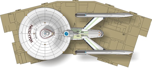
If I recall correctly, I had two turboshafts- one to the port and one to the starboard of the dorsal. Between them was a smallish space that permitted a power conduit enclosed in a square housing. You can see how small it is - about the width of a Burke chair. It isn’t like what we see in TMP, but that was on purpose. The enginery is different. This conduit is bringing deuterium to a fusion rocket, not plasma in a dilithium-lined intermix tube.
Not to get too Trek Tech, or off thread, but one reason for confusion is because I didn’t finish that illustration with callouts and explanatory notes). Green is deuterium, blue is degenerate matter, black is negative energy, and pale orange is antimatter. The ship takes in deuterium via the deflector and nacelles (or is fueled at base with hyperdense degenerate deuterium), converts part of it to anti-deuterium (or is fueled with that too at base), converts the rest to other expendables, etc. It creates its own negative energy via those subspace taps that look kinda like sparkly uniball penises. The negative energy is used to manipulate gravity -everything from life support to inflating the warp bubble.
Last edited:
While providing a convenient place for the characters to have a conversation about the matter at hand.I think we need to acknowledge that the turbolift is there for the same reason as the transporter- as a dramatic expedient to keep the pace moving.
I have the feeling Jeffries never intended the turbolift network to be anywhere as extensive as FJ and the later productions (that were likely inspired by FJ) laid out. Even for a ship as large as the 1701-D it would take less than three minutes to walk from a central lift shaft to the farthest edge of the saucer, for a 289m Enterprise, it's about 45s.
Thanks for that breakdown, it helps a lot. I have a copy of your "Focus on the 1701" notes from about 10 years ago but it is incomplete. One thing mentioned in those notes which I always found interesting concerns the orientation of the Bridge:“Presumably, the turboshaft runs down one side of the dorsal and the vertical power line down the other; do that I have that right?”
If I recall correctly, I had two turboshafts- one to the port and one to the starboard of the dorsal. Between them was a smallish space that permitted a power conduit enclosed in a square housing. You can see how small it is - about the width of a Burke chair. It isn’t like what we see in TMP, but that was on purpose. The enginery is different. This conduit is bringing deuterium to a fusion rocket, not plasma in a dilithium-lined intermix tube.
Not to get too Trek Tech, or off thread, but one reason for confusion is because I didn’t finish that illustration with callouts and explanatory notes). Green is deuterium, blue is degenerate matter, black is negative energy, and pale orange is antimatter. The ship takes in deuterium via the deflector and nacelles (or is fueled at base with hyperdense degenerate deuterium), converts part of it to anti-deuterium (or is fueled with that too at base), converts the rest to other expendables, etc. It creates its own negative energy via those subspace taps that look kinda like sparkly uniball penises. The negative energy is used to manipulate gravity -everything from life support to inflating the warp bubble.
I want to point out that the phaser position on deck 2 is the reason for the 37° rotated bridge, or at least that's the way it seems at this point. The phaser power conduits run back to the area beneath the yellow and red hatch behind the bridge. Though I have this space devoted to a subspace telescope array to harken beck to FJ, it also has a power line running from that hatch that infers power supply or fuel hookup of some kind (probably at a maintenance facility). I did this in order to provide the command decks with an independent power supply, but also because that hatch has the same red and yellow high-visibility colors that are on the round hatch along the keel, and THAT hatch is pretty clearly related to fuel or power. The phaser conduits hook into this B/C deck line, and thus would run squarely into the turboshaft were it not for the rotated bridge. The only other thing to do would be change the turbolift position on the bridge to directly aft, and I am assuming there is a functional reason that is not wanted (possibly related to security, but also perhaps related to the optimal locating of the other stations).
The description seems to imply that the Bridge faces forward, with the phaser power line running underneath it centrally and the turbolift off to one side.
The trouble is, I can't see this in the cutaway image as the Bridge appears to be offset (FJ style) and the turbolift is shown in the usual rear "nub" position. Have I missed something?
Again this may be a result of the "Focus on the 1701" document being incomplete, but you can recall any details I'd be very grateful.
How in the hell, once this thing is built (if ever) are you going to ever be able to see or have access to any part of the interior of the model? I mean currently he has done test models of certain sections but think about the entire ship; there is no way to see anything except the outer decks unless he builds the entire thing from acrylic.
Thanks for that breakdown, it helps a lot….
The description seems to imply that the Bridge faces forward, with the phaser power line running underneath it centrally and the turbolift off to one side.
The trouble is, I can't see this in the cutaway image as the Bridge appears to be offset (FJ style) and the turbolift is shown in the usual rear "nub" position. Have I missed something?
Again this may be a result of the "Focus on the 1701" document being incomplete, but you can recall any details I'd be very grateful.
I think what I was saying was that if that turboshaft is not on the midline, it will run into the two phaser power conduits that are on either side of it and feed into the two (P/S) BC deck phasers (that we see in TAS). Of course we could let them jig and jog around the turboshaft, and I’m not sure I wouldn’t let them if I had it to do over. I am increasingly persuaded that the bridge should just be dropped down a bit further and made straight, with the power conduits snaking their way around the turboshaft.
In the real world, you show up to relieve the watch 15 minutes early, giving time to pass on any relevant orders from the off-going watchstander to the relief.Stagger the shifts,
Also, in principal, travel is down and aft on the port side and up and forward on the starboard side, though in practice, this is lax except during GQs and other such situations where the crew is moving en mass.
I see the 8 foot corridors give enough space for two way foot traffic even during GQs (red alerts) as seen on-screen with shots of crew scrambling during red alerts. We also see more crewmen using the vertical tri-ladders.Also, in principal, travel is down and aft on the port side and up and forward on the starboard side, though in practice, this is lax except during GQs and other such situations where the crew is moving en mass.
As for turbolift bottlenecks:
- Most turbolift stations are probably offset from the turbolift shafts, so a waiting turbolift car doesn't block a turbolift shaft.
- If room permits, I can see dual turbolift shafts running side-by-side.
- If room does not permit, then I can see port side turbolifts only running down and counter-clockwise, and starboard side turbolifts running up and clockwise.
- I can see special turbolift shafts getting highest priority such as the bridge, sickbay, and main engineering, especially if command personnel are in the turbolift car.
- There are fewer turbolift stations and shafts than many others have shown on their deck plans especially in the saucer outer areas; (the crew needs some exercise).
- TOS:The Naked Time, Chaos and disorder on the ship; Kirk, "Clear that tube, will you?"
- ST:TWOK, When Saavik hit the turbolift hold button in mid-shaft travel, she indeed blocked the turbolift shaft; McCoy, "Who's been holding up the damn elevator?".
") .
.
Last edited:
You know what made me question the usefulness of a horizontal turboshaft network? Working in a million-square-foot factory building. The place was longer than the Enterprise, and deeper, front to back, than the saucer diameter. I could walk that latter distance in 30 seconds. A lunchtime walk around the perimeter corridor took 10 minutes. Some of the maintenance crew had electric carts to carry stuff, but the rest of us 900 employees walked between offices. The longest it might take you to get from one end of the building to the other is around 5 minutes.
While elevators are absolutely a necessity, I can't see even needing horizontal shafts any more.
While elevators are absolutely a necessity, I can't see even needing horizontal shafts any more.
You know what made me question the usefulness of a horizontal turboshaft network? Working in a million-square-foot factory building. The place was longer than the Enterprise, and deeper, front to back, than the saucer diameter. I could walk that latter distance in 30 seconds. A lunchtime walk around the perimeter corridor took 10 minutes. Some of the maintenance crew had electric carts to carry stuff, but the rest of us 900 employees walked between offices. The longest it might take you to get from one end of the building to the other is around 5 minutes.
While elevators are absolutely a necessity, I can't see even needing horizontal shafts any more.
Yep. And apart from not being needed, horizontal elevator shafts destroy floor plans. They block everything. You can't walk, say six feet into the next room, you have to walk 120 feet to the end of a horizontal shaft and then another 120 feet back along that same length on the other side.
To ease that problem, the horizontal shafts would need hatches for pedestrian crossing, which is getting ridiculous as to needless complications in ship design and safety.
I read that Navy ships don't even use vertical pedestrian elevator cars, because (among other reasons) you'd get trapped in there if the frame is bent during battle.
The “HULL PRESSURE COMP’TS” schematic is what led me to include limited horizontal tubes. It infers the two main hulls are built up from large “pressure compartments” that might facilitate separation by corridors, ladderways, and maybe even those interfering turboshafts. David Shaw took this idea much further than I did and developed a turboshaft layout that took account of these compartments.
https://i.pinimg.com/originals/85/08/c7/8508c729c8629f099174ae5e220a445f.jpg
https://i.pinimg.com/originals/85/08/c7/8508c729c8629f099174ae5e220a445f.jpg
Similar threads
- Replies
- 482
- Views
- 60K
If you are not already a member then please register an account and join in the discussion!