-
Welcome! The TrekBBS is the number one place to chat about Star Trek with like-minded fans.
If you are not already a member then please register an account and join in the discussion!
You are using an out of date browser. It may not display this or other websites correctly.
You should upgrade or use an alternative browser.
You should upgrade or use an alternative browser.
My TOS shuttlecraft (continued)...
- Thread starter Warped9
- Start date

Re: My TOS shuttelcraft (continued)...
^^ Much appreciated.
My hope is to have a presentation of about two or so minutes long that will present the schematics as well as some photomanips a la my Never seen TOS scenes kind in a slide show style where you can also print out copies of the schematics.
I will have to remake my photomanips for better resolution. And I have to cut and paste some voice clips from episodes on DVD to overlap with some sound f/x.
And note that if it's converted to DIVX format then it could be played on a big screen TV. I put some of my photomanips and large scale drawings on a 4G USB flash drive and plugged it into my 32in. LCD just for fun. Coool!
Last edited:
Re: My TOS shuttelcraft (continued)...
I posted this in another thread, but I think it's relevant here because I'm considering including an edited verssion of this along with my plans:
STAR TREK’S WARP DRIVE
by Ray Lefebvre
The first references to warp flight in Star Trek are in the original pilot episode “The Cage.” In it Captain Pike makes a reference to the proposed ship’s speed as “Our time-warp, factor seven.” This reference doesn’t tell us anything specific, however, it could have inferences. We don’t know if Time-Warp Factor 7 actually refers to the seven times the speed of light or not. But we can begin to draw implications when we consider other references.
Firstly when Spock calls up an image of the Talos star group on his monitor we are shown an image of the Pleides star cluster. This could be totally meaningless, or it could mean that the Pleides star cluster has since become known also as the Talos star group by the 23rd century. And if so then the Talos star group (a.k.a. the Pleides) is 410 light years from Earth. As such then even though we know the Enterprise is a faster-than-light starship, Time-Warp Factor 7 cannot mean only seven times the speed of light because then the Enterprise would have taken more than fifty-eight years to get there from Earth. And so TWF 7 must mean something else.
Additionally there are references to a Rigel 7 and the Vega colonies. If the references are to the same stars presently known as Rigel and Vega that are hundreds of light years away then that reinforces the implication the Enterprise can travel far faster than just a few times the speed of light.
Next there is a reference to an intercepted “old style” radio signal as originating from 18 light years away. Pike decides to investigate and orders the ship to TWF 7. Again TWF 7 cannot be only seven times the speed of light because then it would take more than two and a half years to get to Talos IV. Pike orders the course change with the assurance they can reach Talos within a reasonably short period of time. (And for the record at Warp Factor 7 on my scale they would reach Talos in under three hours, which is a very reasonable period of time). Note that according to the warp formula WF3 given in The Making Of Star Trek the ship would take more than nineteen days to reach Talos at TWF 7.
The final reference to speed in “The Cage” is from Navigator Jose Tyler when he refers to getting back to Earth from Talos IV: “You won’t believe how fast you can get back. The time barrier has been broken. Our new ships can…” Again we’re not being told anything specific, but the inference is that since the Columbia disappeared eighteen years earlier significant advances have been made in stardrive propulsion. The inference is that ships such as the Enterprise are much faster than earlier ones from about two decades earlier. And the reference to a “time barrier” being broken could imply that Pike era ships are a lot faster than ones of the Columbia’s era.
The next references to speed in Star Trek are in the second pilot “Where No Man Has Gone Before.” The Enterprise is said to be at the edge of the galaxy. The implication seems self evident, but in fairness it doesn’t actually specify whether the edge referred to is the galactic rim or the upper or lower planes of the galactic disc. If it’s the rim then the ship is 20,000 light years away, but even if it’s the planes then it’s still easily 1,500 light years away. In either case it’s rather clear the Enterprise is capable of very fast FTL speeds and ones surpassing the oft accepted formula of WF3. Indeed after the ship’s main engines are disabled Captain Kirk makes a reference that Earth bases once only days away were now years in the distance.
That last reference needs to be examined because if actually without any FTL warp speed whatsoever then distant Earth bases are certainly more than just years away, they would be centuries to thousands of years away if the ship was then restricted solely to slower-than-light speeds. Recall that Spock says Delta Vega is only “a few light days away.” Well it’s only light days if you can travel at least at the speed of light or better. And so perhaps what is really being said in WNMHGB is that the damaged ship’s engines are precluding normal warp speeds, but not very low warp speeds such as under WF 1.
This idea goes pretty much unsupported until a reference to Warp .5 in ST-TMP. Now if the crippled Enterprise in WNMHGB can still achieve a speed of up to WF .9 then it can reach Delta Vega within two weeks if it’s within five light years distance. That could be close enough to be accepted as “a few light days away.”
Something else established is that a starship Valiant disappeared some two hundred years earlier and evidence places it at the edge of the galaxy (whichever “edge” that may be). Regardless it means some form of FTL drive must have been available two centuries earlier or how else did the Valiant get out there?—something which is never explained.
Throughout the series there are references to numerous star systems that are known in astronomy today. These are stars that the Enterprise is referenced to actually have been to during its voyage--and if they are accepted as being the same or related to stars we know today then it is telling.
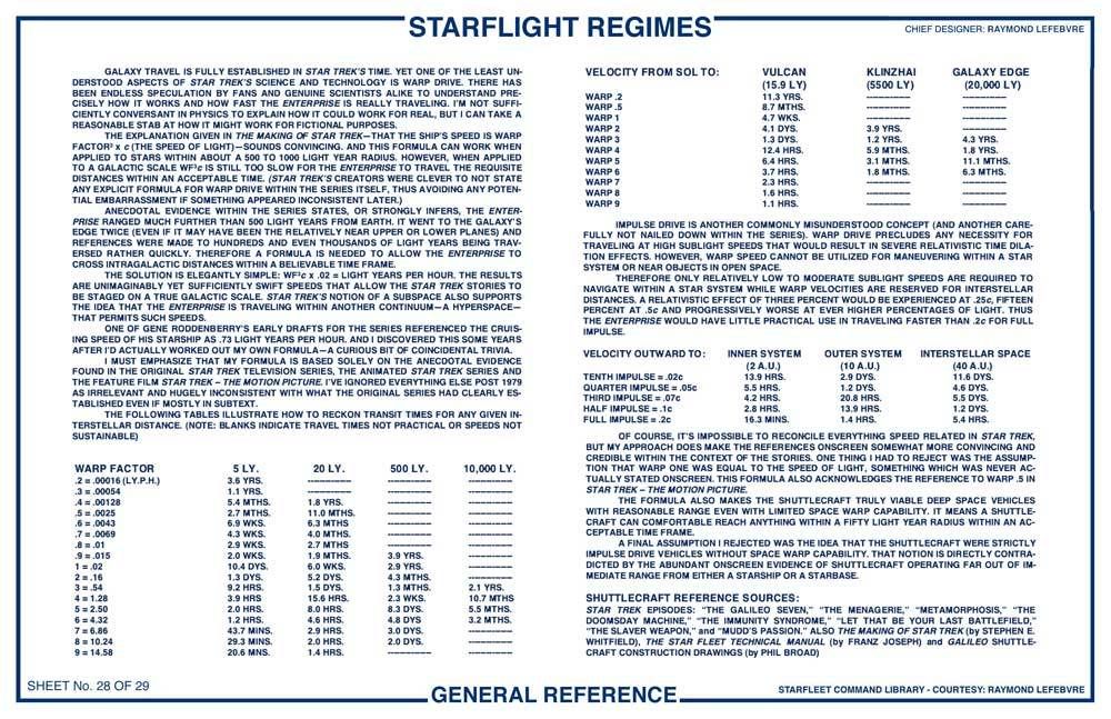
Rigel = 900 ly. (“The Cage” and “Mudd’s Women”)
Vega = 26 ly. (“The Cage”)
Galaxy edge = 20,000 ly. or 1,500 ly. (“Where No Man Has Gone Before,” “By Any Other Name” and “Beyond The Farthest Star”)
Omicron Ceti = 170 ly. (“This Side Of Paradise”)
Ceti Alpha = 130 ly. (“Space Seed”)
(Vulcan) 40 Eridani = 16 ly. {“Amok Time”)
Altair = 17 ly. (“Amok Time”)
Pollux = 250 ly. (“Who Mourns For Adonis?”)
Gamma Trianguli = 84 ly. (“The Apple”)
Gamma Hydra = 110 ly. (“The Deadly Years”)
Alpha Carinae = 71 ly. (“The Ultimate Computer”)
Sigma Draconis = 19 ly. (“Spock’s Brain”)
Beta Aurigae = 80 ly. (“Turnabout Intruder”)
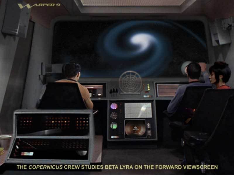
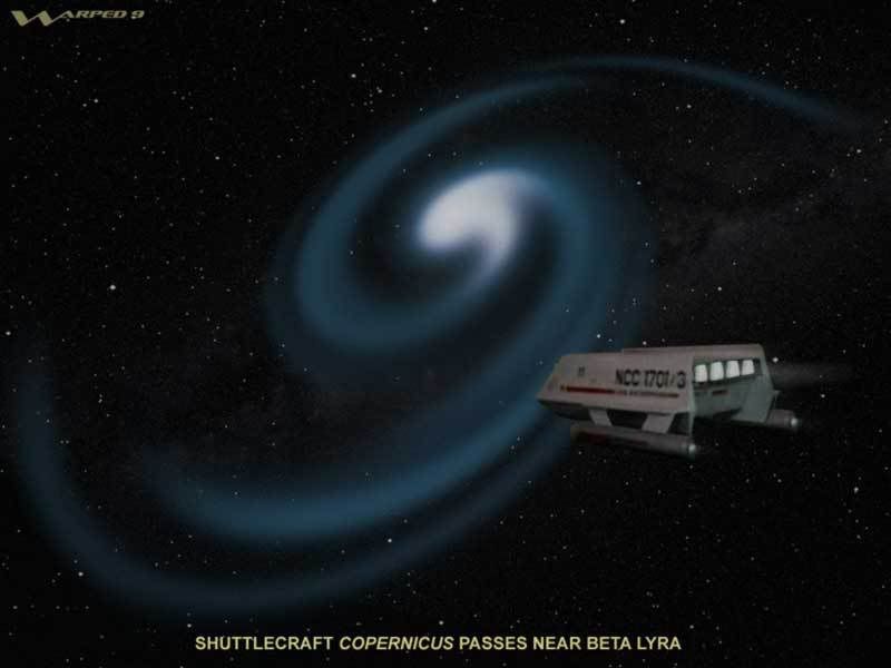
Beta Lyrae = 210 ly. (“The Slaver Weapon”)
Galaxy centre = 30,000 ly. (“The Magicks Of Megas-Tu”)
The aforementioned locations are all over the sky. If these are accepted as the stars we know today then the Enterprise would have to be able to do some serious cruising to get from place to place within the time frames implied in the episodes. And even if they’re not supposed to be the same locales we know of today then even so the series’ writers were still unwittingly suggesting the Enterprise was ranging over at least hundreds and perhaps thousands of light years. This idea is supported by the occasional spoken reference to “throughout the galaxy,” even if this was a degree of exaggeration on the part of the characters.
You cannot just dismiss it all as sloppy writing and therefore meaningless when the sheer amount of direct and indirect references is conveying something substantial as a whole. Why use real astronomical references if not to at least suggest where your stories are taking place? Science fiction writers since the beginning and still presently use actual known stellar references to lend their stories a measure of credibility. Why should Star Trek be any different?
Additionally:
“Balance Of Terror” (Stardate 1709.1) – The important idea here is that ships from a century earlier were significantly less advanced. And it reinforces the idea conveyed in “The Cage” that some sort of “time barrier” was surpassed in more recent decades. The “time barrier” idea may actually be only something of a colloquial expression, but it seems to be intended to convey the idea of a significant advancement in stardrive propulsion within the last twenty years.
“The Squire Of Gothos” (Stardate 2124.5) – The real reference here is that Gothos is supposedly 900 light years from Earth despite the question of Trelane’s telescopic observations. At this time Star Trek had not yet firmly established when it was set, but the references in this episode suggest the 27th century since Trelane refers to things he studied from the around the 17th to 18th century era.
“The Conscience Of The King” (Stardate 2816.6) – The Enterprise is diverted three light years off her course to respond to Dr. Thomas Leighton’s summons. The inference in the episode is that while inconvenient it didn’t take too long for the Enterprise to make such a detour.
“The Galileo Seven” (Stardate 2821.5) – The Murasaki 312 quasar effect has encompassed at least four star systems and the Enterprise has no idea where in all of that the shuttlecraft Galileo has disappeared. The shuttlecraft would have had at least some warp capability for those star systems to have been within its range within a rather short period of time because the Enterprise could not afford to tarry for very long before moving on to meet a deadline.
“The Menagerie” (Stardate 3012.4) – The Enterprise travels from Starbase 11 to Talos 4 within what seems to be barely a few days. And this idea is reinforced by Spock’s reference that Talos 4 is only a few days away. This suggests that Starbase 11 is possibly within a couple of hundred light years of the Talos star group. This episode also reaffirms the idea that shuttlecraft are warp capable. Otherwise it would be totally pointless for a sublight limited shuttlecraft to attempt to chase the Enterprise warping out of orbit.
“Arena” (Stardate 3045.6) – The Metrons displace the Enterprise 900 parsecs (2934 ly.).
“Tomorrow Is Yesterday” (Stardate 3113.2) – The Enterprise has returned to Earth even if it is also back in time. But Earth still had to be within a reasonable range because even 200-300 years wouldn’t account for much stellar drift.
“Space Seed” (Stardate 3141.9) – The question here is: how fast was the Botany Bay traveling when it left Earth? That would tell us how far it got by the time the Enterprise found it 200 years later. The Botany Bay group is landed in the nearby Ceti Alpha system which is 130 light years away. That might suggest the Botany Bay was traveling at something like forty to sixty percent of light. Not bad for a 1990s era spacecraft. (-: Another point, though, is that dating the Botany Bay from the 1990s and stating the ship was found about two centuries later sets Star Trek around the late 22nd to early 23rd century. It’s also established here that humanity used sleeper ships until 2018, which suggests that something happened that made sleeper ships obsolete.
“The Gamesters of Triskelion” (Stardate 3211.7) – The Enterprise crosses 11.63 light years in a rather short period of time between Warp 2 and Warp 7. By my scale this would have taken less than two hours which fits with what is implied in the episode.
“Metamorphosis” (Stardate 3219.8) – The shuttlecraft is obviously far out of range of immediate help from the Enterprise when it is intercepted by the Companion. The shuttlecraft again needed warp drive to perform its task or it would have been simply faster to have had the Enterprise pick up Commissioner Hedford. What is also established here is that the space warp was available in some form at least 150 years earlier.
“Amok Time” (Stardate 3372.7) – The Enterprise somehow has to manage the distance between Vulcan (40 Eridani) and Altair 6 within the space of scant days. Now these two stars are both only about 16 light years from Earth, but they are definitely not in the same part of the sky. As such Kirk still has to push the Enterprise to the maximum.
“This Side Of Paradise” (Stardate 3417.3) – Omicron Ceti is 170 light years from Earth, if it is indeed the same star we know of today. And the colonists supposedly took over a year to get there. That would mean the colonists were traveling aboard a very slow ship. Or if it’s a different star than the one we know then the colonists could have been traveling at about Warp 2 to someplace within 500 light years.
“Friday’s Child” (Stardate 3497.2) – There is a reference to a freighter not being able to go more than about Warp 2. By my reckoning that would mean the freighter had a practical yet rather limited range of about 150-200 light years or so.
“Obsession” (Stardate 3619.2) – The Enterprise has to rendezvous with the Yorktown within forty-eight hours while chasing the cloud creature between planets Argus 10 and Tychos 4 which are supposedly more than a thousand light years apart.
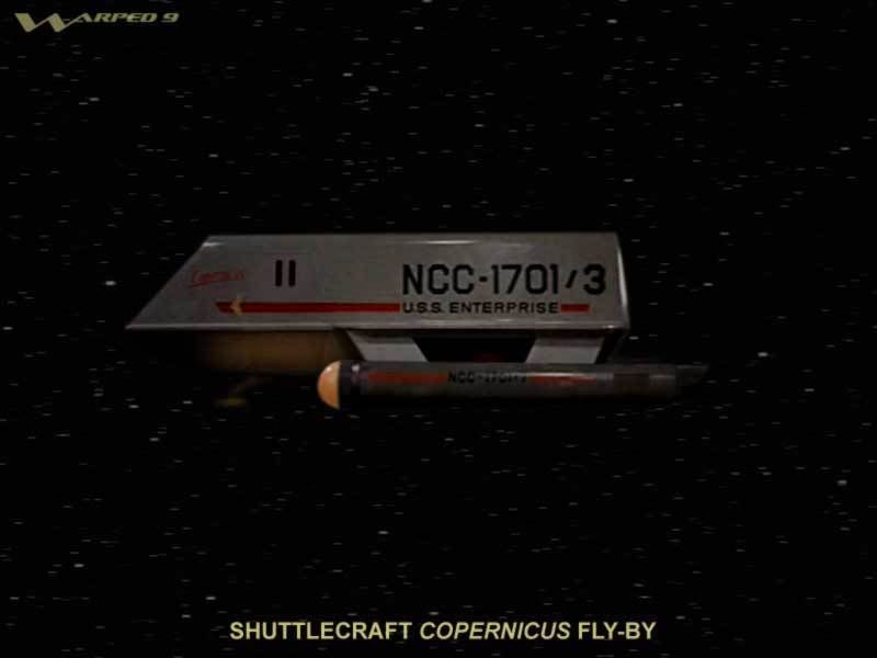
“The Slaver Weapon” (Stardate 4187.3) – The shuttlecraft Copernicus needed warp drive to have conducted its mission and to have been out of range of immediate aid from the Enterprise.
“I, Mudd” (Stardate 4513.3) – The Enterprise travels for four days at Warp 7 to a planet that has never been charted. By my reckoning they went more than 650 light years.
“By Any Other Name” (Stardate 4657.5) – The Enterprise returns to the edge of the galaxy within a rather short period of time. Thus the ship is already out near the rim or it’s piercing the nearer upper or lower plane. The interesting wrinkle here is that the Kelvans claim their voyage from Andromeda took three hundred years. And Kirk claims the Enterprise couldn’t reach Andromeda for thousands of years. Well even at WF3 at Warp 9 it would take the Enterprise over 3000 years to reach Andromeda. Even at the Kelvans modified Warp 11 it would still take more than 1600 years. On my scale at Warp 11 it would take only ten years or seventeen years at Warp 9. Two things occur to me here: either intergalactic space is somehow different than interstellar space in such a way that affects warp flight and/or the Kelvans aren’t as advanced as they like to claim at least in regards to starflight propulsion and Kirk was trying to mislead them.
“Return To Tomorrow” (Stardate 4768.3) – The Enterprise travels hundreds of light years beyond where any known vessel has ever gone.
“Assignment: Earth” – Again back in time, but the ship still returns to Earth.
“That Which Survives” – The Enterprise crosses 990.7 light years at Warp 8 and then up to Warp 14.1. By my reckoning the trip would have taken at least four days at Warp 8 and only about eighteen hours at Warp 14. But essentially they make the crossing in a remarkably short period of time of only a couple of days.
“Mudd’s Passion” (Stardate 4978.5) – Harry Mudd steals a shuttlecraft with the intent of eventually making it to a more hospitable star system. The craft would have needed warp drive for Mudd to have made the trip within his lifetime.
“Beyond The Farthest Star” (Stardate 5521.3) – The Enterprise is supposedly on the galactic rim.
“Let That Be Your Last Battlefield” (Stardate 5730.2) – A shuttlecraft stolen weeks earlier from a starbase is intercepted. Again the idea of shuttlecraft with warp drive is reaffirmed or how else could it have gotten in deep space?
“The Magicks Of Megas-Tu” – The Enterprise travels towards the center of the galaxy.
Star Trek – The Motion Picture (Stardate 7412.6) – Kirk orders Warp .5 to clear the Sol system even though the warp drive is supposedly still offline. Perhaps what is really meant here is that higher and more routine warp speeds are unavailable until the new engines are properly calibrated to sustain the necessary space warp fields for higher warp velocities. TMP also implies that the events are set in the latter part of the 23rd century.
While there is very little explicitly specific in reference throughout TOS-TAS-TMP the sheer weight of anecdotal evidence supports that the Enterprise is capable of incredible speeds for the stories to take place within the implied time frames of the stories. Even with a consistent formula as I’ve worked out there are still inconsistencies that arise simply because the TOS writers were not practiced astronomers and experienced interstellar navigators. They were trying to tell stories with a ring of credibility yet not rigidly plotted out in terms of locations and requisite travel times.
I posted this in another thread, but I think it's relevant here because I'm considering including an edited verssion of this along with my plans:
STAR TREK’S WARP DRIVE
by Ray Lefebvre
The first references to warp flight in Star Trek are in the original pilot episode “The Cage.” In it Captain Pike makes a reference to the proposed ship’s speed as “Our time-warp, factor seven.” This reference doesn’t tell us anything specific, however, it could have inferences. We don’t know if Time-Warp Factor 7 actually refers to the seven times the speed of light or not. But we can begin to draw implications when we consider other references.
Firstly when Spock calls up an image of the Talos star group on his monitor we are shown an image of the Pleides star cluster. This could be totally meaningless, or it could mean that the Pleides star cluster has since become known also as the Talos star group by the 23rd century. And if so then the Talos star group (a.k.a. the Pleides) is 410 light years from Earth. As such then even though we know the Enterprise is a faster-than-light starship, Time-Warp Factor 7 cannot mean only seven times the speed of light because then the Enterprise would have taken more than fifty-eight years to get there from Earth. And so TWF 7 must mean something else.
Additionally there are references to a Rigel 7 and the Vega colonies. If the references are to the same stars presently known as Rigel and Vega that are hundreds of light years away then that reinforces the implication the Enterprise can travel far faster than just a few times the speed of light.
Next there is a reference to an intercepted “old style” radio signal as originating from 18 light years away. Pike decides to investigate and orders the ship to TWF 7. Again TWF 7 cannot be only seven times the speed of light because then it would take more than two and a half years to get to Talos IV. Pike orders the course change with the assurance they can reach Talos within a reasonably short period of time. (And for the record at Warp Factor 7 on my scale they would reach Talos in under three hours, which is a very reasonable period of time). Note that according to the warp formula WF3 given in The Making Of Star Trek the ship would take more than nineteen days to reach Talos at TWF 7.
The final reference to speed in “The Cage” is from Navigator Jose Tyler when he refers to getting back to Earth from Talos IV: “You won’t believe how fast you can get back. The time barrier has been broken. Our new ships can…” Again we’re not being told anything specific, but the inference is that since the Columbia disappeared eighteen years earlier significant advances have been made in stardrive propulsion. The inference is that ships such as the Enterprise are much faster than earlier ones from about two decades earlier. And the reference to a “time barrier” being broken could imply that Pike era ships are a lot faster than ones of the Columbia’s era.
The next references to speed in Star Trek are in the second pilot “Where No Man Has Gone Before.” The Enterprise is said to be at the edge of the galaxy. The implication seems self evident, but in fairness it doesn’t actually specify whether the edge referred to is the galactic rim or the upper or lower planes of the galactic disc. If it’s the rim then the ship is 20,000 light years away, but even if it’s the planes then it’s still easily 1,500 light years away. In either case it’s rather clear the Enterprise is capable of very fast FTL speeds and ones surpassing the oft accepted formula of WF3. Indeed after the ship’s main engines are disabled Captain Kirk makes a reference that Earth bases once only days away were now years in the distance.
That last reference needs to be examined because if actually without any FTL warp speed whatsoever then distant Earth bases are certainly more than just years away, they would be centuries to thousands of years away if the ship was then restricted solely to slower-than-light speeds. Recall that Spock says Delta Vega is only “a few light days away.” Well it’s only light days if you can travel at least at the speed of light or better. And so perhaps what is really being said in WNMHGB is that the damaged ship’s engines are precluding normal warp speeds, but not very low warp speeds such as under WF 1.
This idea goes pretty much unsupported until a reference to Warp .5 in ST-TMP. Now if the crippled Enterprise in WNMHGB can still achieve a speed of up to WF .9 then it can reach Delta Vega within two weeks if it’s within five light years distance. That could be close enough to be accepted as “a few light days away.”
Something else established is that a starship Valiant disappeared some two hundred years earlier and evidence places it at the edge of the galaxy (whichever “edge” that may be). Regardless it means some form of FTL drive must have been available two centuries earlier or how else did the Valiant get out there?—something which is never explained.
Throughout the series there are references to numerous star systems that are known in astronomy today. These are stars that the Enterprise is referenced to actually have been to during its voyage--and if they are accepted as being the same or related to stars we know today then it is telling.
Rigel = 900 ly. (“The Cage” and “Mudd’s Women”)
Vega = 26 ly. (“The Cage”)
Galaxy edge = 20,000 ly. or 1,500 ly. (“Where No Man Has Gone Before,” “By Any Other Name” and “Beyond The Farthest Star”)
Omicron Ceti = 170 ly. (“This Side Of Paradise”)
Ceti Alpha = 130 ly. (“Space Seed”)
(Vulcan) 40 Eridani = 16 ly. {“Amok Time”)
Altair = 17 ly. (“Amok Time”)
Pollux = 250 ly. (“Who Mourns For Adonis?”)
Gamma Trianguli = 84 ly. (“The Apple”)
Gamma Hydra = 110 ly. (“The Deadly Years”)
Alpha Carinae = 71 ly. (“The Ultimate Computer”)
Sigma Draconis = 19 ly. (“Spock’s Brain”)
Beta Aurigae = 80 ly. (“Turnabout Intruder”)
Beta Lyrae = 210 ly. (“The Slaver Weapon”)
Galaxy centre = 30,000 ly. (“The Magicks Of Megas-Tu”)
The aforementioned locations are all over the sky. If these are accepted as the stars we know today then the Enterprise would have to be able to do some serious cruising to get from place to place within the time frames implied in the episodes. And even if they’re not supposed to be the same locales we know of today then even so the series’ writers were still unwittingly suggesting the Enterprise was ranging over at least hundreds and perhaps thousands of light years. This idea is supported by the occasional spoken reference to “throughout the galaxy,” even if this was a degree of exaggeration on the part of the characters.
You cannot just dismiss it all as sloppy writing and therefore meaningless when the sheer amount of direct and indirect references is conveying something substantial as a whole. Why use real astronomical references if not to at least suggest where your stories are taking place? Science fiction writers since the beginning and still presently use actual known stellar references to lend their stories a measure of credibility. Why should Star Trek be any different?
Additionally:
“Balance Of Terror” (Stardate 1709.1) – The important idea here is that ships from a century earlier were significantly less advanced. And it reinforces the idea conveyed in “The Cage” that some sort of “time barrier” was surpassed in more recent decades. The “time barrier” idea may actually be only something of a colloquial expression, but it seems to be intended to convey the idea of a significant advancement in stardrive propulsion within the last twenty years.
“The Squire Of Gothos” (Stardate 2124.5) – The real reference here is that Gothos is supposedly 900 light years from Earth despite the question of Trelane’s telescopic observations. At this time Star Trek had not yet firmly established when it was set, but the references in this episode suggest the 27th century since Trelane refers to things he studied from the around the 17th to 18th century era.
“The Conscience Of The King” (Stardate 2816.6) – The Enterprise is diverted three light years off her course to respond to Dr. Thomas Leighton’s summons. The inference in the episode is that while inconvenient it didn’t take too long for the Enterprise to make such a detour.
“The Galileo Seven” (Stardate 2821.5) – The Murasaki 312 quasar effect has encompassed at least four star systems and the Enterprise has no idea where in all of that the shuttlecraft Galileo has disappeared. The shuttlecraft would have had at least some warp capability for those star systems to have been within its range within a rather short period of time because the Enterprise could not afford to tarry for very long before moving on to meet a deadline.
“The Menagerie” (Stardate 3012.4) – The Enterprise travels from Starbase 11 to Talos 4 within what seems to be barely a few days. And this idea is reinforced by Spock’s reference that Talos 4 is only a few days away. This suggests that Starbase 11 is possibly within a couple of hundred light years of the Talos star group. This episode also reaffirms the idea that shuttlecraft are warp capable. Otherwise it would be totally pointless for a sublight limited shuttlecraft to attempt to chase the Enterprise warping out of orbit.
“Arena” (Stardate 3045.6) – The Metrons displace the Enterprise 900 parsecs (2934 ly.).
“Tomorrow Is Yesterday” (Stardate 3113.2) – The Enterprise has returned to Earth even if it is also back in time. But Earth still had to be within a reasonable range because even 200-300 years wouldn’t account for much stellar drift.
“Space Seed” (Stardate 3141.9) – The question here is: how fast was the Botany Bay traveling when it left Earth? That would tell us how far it got by the time the Enterprise found it 200 years later. The Botany Bay group is landed in the nearby Ceti Alpha system which is 130 light years away. That might suggest the Botany Bay was traveling at something like forty to sixty percent of light. Not bad for a 1990s era spacecraft. (-: Another point, though, is that dating the Botany Bay from the 1990s and stating the ship was found about two centuries later sets Star Trek around the late 22nd to early 23rd century. It’s also established here that humanity used sleeper ships until 2018, which suggests that something happened that made sleeper ships obsolete.
“The Gamesters of Triskelion” (Stardate 3211.7) – The Enterprise crosses 11.63 light years in a rather short period of time between Warp 2 and Warp 7. By my scale this would have taken less than two hours which fits with what is implied in the episode.
“Metamorphosis” (Stardate 3219.8) – The shuttlecraft is obviously far out of range of immediate help from the Enterprise when it is intercepted by the Companion. The shuttlecraft again needed warp drive to perform its task or it would have been simply faster to have had the Enterprise pick up Commissioner Hedford. What is also established here is that the space warp was available in some form at least 150 years earlier.
“Amok Time” (Stardate 3372.7) – The Enterprise somehow has to manage the distance between Vulcan (40 Eridani) and Altair 6 within the space of scant days. Now these two stars are both only about 16 light years from Earth, but they are definitely not in the same part of the sky. As such Kirk still has to push the Enterprise to the maximum.
“This Side Of Paradise” (Stardate 3417.3) – Omicron Ceti is 170 light years from Earth, if it is indeed the same star we know of today. And the colonists supposedly took over a year to get there. That would mean the colonists were traveling aboard a very slow ship. Or if it’s a different star than the one we know then the colonists could have been traveling at about Warp 2 to someplace within 500 light years.
“Friday’s Child” (Stardate 3497.2) – There is a reference to a freighter not being able to go more than about Warp 2. By my reckoning that would mean the freighter had a practical yet rather limited range of about 150-200 light years or so.
“Obsession” (Stardate 3619.2) – The Enterprise has to rendezvous with the Yorktown within forty-eight hours while chasing the cloud creature between planets Argus 10 and Tychos 4 which are supposedly more than a thousand light years apart.
“The Slaver Weapon” (Stardate 4187.3) – The shuttlecraft Copernicus needed warp drive to have conducted its mission and to have been out of range of immediate aid from the Enterprise.
“I, Mudd” (Stardate 4513.3) – The Enterprise travels for four days at Warp 7 to a planet that has never been charted. By my reckoning they went more than 650 light years.
“By Any Other Name” (Stardate 4657.5) – The Enterprise returns to the edge of the galaxy within a rather short period of time. Thus the ship is already out near the rim or it’s piercing the nearer upper or lower plane. The interesting wrinkle here is that the Kelvans claim their voyage from Andromeda took three hundred years. And Kirk claims the Enterprise couldn’t reach Andromeda for thousands of years. Well even at WF3 at Warp 9 it would take the Enterprise over 3000 years to reach Andromeda. Even at the Kelvans modified Warp 11 it would still take more than 1600 years. On my scale at Warp 11 it would take only ten years or seventeen years at Warp 9. Two things occur to me here: either intergalactic space is somehow different than interstellar space in such a way that affects warp flight and/or the Kelvans aren’t as advanced as they like to claim at least in regards to starflight propulsion and Kirk was trying to mislead them.
“Return To Tomorrow” (Stardate 4768.3) – The Enterprise travels hundreds of light years beyond where any known vessel has ever gone.
“Assignment: Earth” – Again back in time, but the ship still returns to Earth.
“That Which Survives” – The Enterprise crosses 990.7 light years at Warp 8 and then up to Warp 14.1. By my reckoning the trip would have taken at least four days at Warp 8 and only about eighteen hours at Warp 14. But essentially they make the crossing in a remarkably short period of time of only a couple of days.
“Mudd’s Passion” (Stardate 4978.5) – Harry Mudd steals a shuttlecraft with the intent of eventually making it to a more hospitable star system. The craft would have needed warp drive for Mudd to have made the trip within his lifetime.
“Beyond The Farthest Star” (Stardate 5521.3) – The Enterprise is supposedly on the galactic rim.
“Let That Be Your Last Battlefield” (Stardate 5730.2) – A shuttlecraft stolen weeks earlier from a starbase is intercepted. Again the idea of shuttlecraft with warp drive is reaffirmed or how else could it have gotten in deep space?
“The Magicks Of Megas-Tu” – The Enterprise travels towards the center of the galaxy.
Star Trek – The Motion Picture (Stardate 7412.6) – Kirk orders Warp .5 to clear the Sol system even though the warp drive is supposedly still offline. Perhaps what is really meant here is that higher and more routine warp speeds are unavailable until the new engines are properly calibrated to sustain the necessary space warp fields for higher warp velocities. TMP also implies that the events are set in the latter part of the 23rd century.
While there is very little explicitly specific in reference throughout TOS-TAS-TMP the sheer weight of anecdotal evidence supports that the Enterprise is capable of incredible speeds for the stories to take place within the implied time frames of the stories. Even with a consistent formula as I’ve worked out there are still inconsistencies that arise simply because the TOS writers were not practiced astronomers and experienced interstellar navigators. They were trying to tell stories with a ring of credibility yet not rigidly plotted out in terms of locations and requisite travel times.
Re: My TOS shuttelcraft (continued)...
Conclusion:
Now flashing forward to the early seasons of Star Trek: The Next Generation there really isn’t much to contradict what TOS appears to have established in terms of how fast warp speeds appear to be. That is until you hit the reference in “Q, Who?” stating the 1701D will take two years at maximum warp to cross only 7,000 light years. That is a significant inconsistency with what TOS had already established even if much of it indirectly. The only conclusion is either the 1701D era ships aren’t as fast as they’re suggested to be or TNG isn’t of the same continuity as TOS. It beggars credibility to simply dismiss the weight of evidence in TOS as sloppy writing. One can applaud the TNG writers for trying to be more consistent for the sake of credibility, but it was inexcusable to wholly ignore what had already been established.
You could dismiss TNG as an alternate continuity bolstered by other small inconsistencies on continuity with TOS. But those other inconsistencies can be reconciled in something of a pretzel fashion and accept that the TNG era ships are actually not much faster than those of the TOS era. Perhaps something amiss and unsaid is happening in “Q, Who?” to rationalize the slower speed because the 1701D would be doing no better than about Warp 2.5 by my scale. Or maybe while the 1701D was displaced only 7,000 light years it was still already tens of thousands of light years from Federation territory to which it would take two years to return from where Q had sent them, particularly if they had to circumvent the intense radiation of Shapley Center at the heart of the galaxy.
I prefer the latter scenario since it supports the big concept of Star Trek set on a galactic like scale and the Federation starships ranging far into unknown regions. It also makes the galaxy more credible by avoiding the idea that inhabited worlds are crowded around practically every corner. It’s a little more of a rare Earth type concept which makes the galaxy seem more vast and strange. Later TNG and the three later spinoff series pretty much ruined that concept.
Several years ago I heard of an idea bandied about by fans that perhaps warp values mightn’t be consistent in all parts of interstellar space. This idea would be similar to variables in the speed of sound depending on your altitude here on Earth. This variable might reconcile some of the inconsistencies in regards to trip times and warp values referenced throughout the series. It does allow you to fudge it to some degree. But it doesn’t really reconcile the inconsistency between TOS’ implied speeds and the TNG implied speeds if the TNG era ships are really supposed to be a lot faster.
Published Star Trek fiction is not considered “official” in regards to the onscreen stories, but at least two authors picked up on the general idea from which I extrapolated my warp scale. The first was James Blish in his novel Spock Must Die! where he had the Enterprise positioned on the opposite side of the galaxy wherein it would take three months to get back to Organia and near Federation territory. The other was John M. Ford’s The Final Reflection which stated that his Klingon characters took several months or so to travel from the Klingon homeworld to Earth at Warp 4 in a story set some thirty years or so before the TOS era.
Blish also based his adaptations of the TOS episodes on early drafts of the scripts. Sometimes these adaptations differed distinctly from the aired episodes. In his narrations he also included references that were not heard in the aired episodes, but were still consistent with what the final episodes established. The first specific was in regards to the Earth/Romulan war mentioned in “Balance Of Terror.” In Blish’s adaptation of the episode it says the war happened a hundred to seventy-five years earlier and lasted for twenty-five years. And that it was fought with primitive ships and weaponry. None of what Blish says contradicts what is established in the aired episode and indeed it actually reinforces it. Note that Diane Duane’s later Rihansuu books extrapolated from James Blish’s adaptation.
Another reference is found in Blish’s adaptation of “Miri.” Based on an earlier draft of the script Blish states that the inhabitants of Miri’s planet were actually descendents of disgruntled Earth colonists. Those colonists could have come from the very first colonization wave of the 21st century. And it makes a measure of sense since the planet’s ruins could be roughly analogous to Earth of the 21st century.
Over the years after I put all of this together into some reasonably coherent general picture. Yet in no way do I claim this is how the TOS creators consciously and deliberately conceived this sequence of Star Trek history:
In the early 1990s Earth had continued developing space flight after the successful Apollo program of the late ‘60s and early ‘70s. At that point Earth had primitive ships that could barely get out of the solar system. The idea of sleeper ships may or may not have been actually used in general practice to leave the solar system, but we know at least one ship, the Botany Bay, managed to reach about fifty percent of light in leaving the system and was subsequently found some two and a half centuries later. Around 2018 some more advanced propulsion system was developed that obviated the need for sleeper ships. My speculation is some form of fast relativistic propulsion that could drive ships to high percentages of light thereby exploiting the advantages of significant time dilation and subsequently putting the nearest star systems within reach.
Sometime around the mid 21st century a young scientist named Zefram Cochrane develops the first apparently successful space warp. This would immediately negate any further need for fast relativistic travel. However, the first warp drives were not very advanced and even nearby star systems were still a respectable time away. Even so the first colonization efforts get underway as humanity steps into the galaxy. During the latter 21st and into early 22nd century three things happen: humans encounter Vulcans, humans encounter and fight Kzinti, and the Valiant mentioned in WNMHGB disappears as does a Bonaventure mentioned in TAS’ “Time Trap.”
The Bonaventure mentioned in “Time Trap” is said to have been the first ship with warp drive that disappeared on its third voyage 150 years earlier. This seems rather inconsistent with the established reference that the Valiant, a “galactic survey cruiser,” disappeared about two centuries prior to WNMHGB. That’s a fifty year inconsistency. However, it’s also possible that the Bonaventure is indeed the first ship with a recognized space warp drive that does predate the Valiant, but that the Bonaventure was some decades old when it finally vanished. A ship with rather low warp capability could have had voyages that were years long in duration such that it still could have disappeared on its third major voyage. The situation at the time could also be blurred by history in regards to when it became known the ship was actually overdue and missing and accepted as lost.
During the mid 22nd century Earth ships have warp drive, but it’s still on the slow side. Even so humanity is spreading out into the local interstellar area. Then humanity encounters an unknown and unseen race only known as Romulans and a bloody conflict lasting many years ensues. Around this time a ship named Horizon disappears and the implication is that subspace radio is just coming into use and not all ships (such as the Horizon) have it yet. This point needs to be emphasized. Up until the late 22nd century not having any decent means of superluminal communications is going to be a real hindrance in terms of any deep space operations. Any communications restricted to the speed of light will only be convenient if you’re within light seconds, minutes, hours, days or at best weeks of your intended recipient. Otherwise it will take years for a signal to reach home. If you get into trouble and manage to get a signal off no one will likely know (or send help) until years or even decades after the fact. For this reason alone many ships probably went missing and never heard from again until ages later if at all.
The Earth/Romulan war possibly encourages the establishing of an interstellar union known as The United Federation Of Planets. The Federation and subsequently its military/exploration arm known as Star Fleet are established during the latter part of the 22nd century or perhaps even the early part of the 23rd. There are vague inferences in TOS that the UFP and Starfleet may actually be only a few decades old and not a century. Already existent space organizations such as Earth’s United Earth Space Probe Agency continue to operate until at least the mid 23rd century. And finally sometime in the very early part of the 23rd century humanity encounters the Klingon Empire resulting in subsequent decades of distrust and animosity.
Also sometime during the first half of the 23rd century some very significant advances in warp propulsion arose. It may well be connected to the work of Dr. Richard Daystrom. Perhaps Daystrom’s new duotronic computer systems in conjunction with the use of dilithium now allow sufficiently stable fields for much higher warp velocities. Effectively some sort of “time barrier” is broken that now really opens up the galaxy. Daystrom’s systems may also greatly facilitate interstellar navigation at higher warp speeds, or perhaps even making navigating while at warp even possible wherein it may have not been earlier. The gist of this is that prior to these advancements I think humanity was relegated pretty much to an area within only a few hundred light years of Earth and that was stretching it. Afterwards the galaxy was really opened up as never before imagined speeds became available.
If I factor in early TNG references then it really doesn’t upset the cart too much. TNG refers to some manner of societal upheaval during the first half of the 21st century, possibly originating in the Eugenics wars of the 1990s. Perhaps even a handful of nuclear bombs were used that supports TNG’s reference to an atomic horror yet doesn’t specifically contradict TOS’ assertion that humanity had avoided an atomic holocaust. Essentially quite a few people may have died, but the planet was far from being reduced to a radioactive waste. There was obviously enough still functioning governmental infrastructure for Zefram Cochrane to develop his space warp and the first ships to get launched. If the planet had indeed been reduced to bare existence then there would have been absolutely no support system in place to get Cochrane off the ground. People would have been focused wholly on just surviving. At any rate Earth’s World War III originates in the 1990s and lasts into the very early 21st century. The Vulcans may or may not have had a hand in helping Earth along, but I’m inclined to suspect Vulcans would have pretty much steered clear of the apparently violent inhabitants of the Sol system until we got our act together. All we really know is that by recognizing Spock as a Vulcan in TOS then Zefram Cochrane either encountered Vulcans firsthand or at least knew of them during the latter 21st or early 22nd century.
Another possibility is that Cochrane didn’t develop his space warp on Earth, but rather on Alpha Centauri. Recall that Kirk refers to him as Zefram Cochrane of Alpha Centauri. Regardless it means that at some point Cochrane is able to get to Alpha Centauri sometime during the 21st century and his named is widely recognized to be connected with the place.
Anyway that’s my take on it. And I know it contradicts what has since been “officially” established during latter TNG and throughout DS9, VOY and then ENT. But I stand by the notion that the timeline was usurped somewhere along the way either by nefarious or unwitting tampering and/or by inattentive and uncaring Trek writers.
It’s very easy and perhaps even somewhat fashionable for many to casually dismiss fanon. But over the years many interested and devoted fans painstakingly pieced together the clues of Star Trek’s continuity to form a generally coherent whole. They pondered, discussed, debated and even argued over the interpretation of all the given clues, and so it’s somewhat understandable that a lot us got upset when we saw TPTB outright overlook and overrule what seemed so obvious to us for the sake of expediency.
From my perspective the fact that TPTB fashioned a very different “official” continuity does not negate what I and others have managed to piece together. I see fanon’s general continuity as the more likely original timeline that was later corrupted in some manner. Therefore the “history” depicted in ENT and elsewhere in TNG, DS9 and VOY is not the same history that will lead to the TOS and early TNG we are already familiar with.
And that last point will likely be confirmed in the forthcoming Trek XI movie.
The initial objective of my thread was in regards to the nature of warp drive in the TOS era. But it’s inevitable that the issue of Star Trek’s warp drive will lead to the discussion of continuity, because as in our own world speed of travel and technology will have an indisputable influence on society and history.
Re: My TOS shuttelcraft (continued)...
TNG did change the rules quite a bit. In TOS crossing the galaxy seemed to be limited only by the dangers of unknown territory or damage. When TFF had the ship warp to the center of the galaxy in mere days rather than decades, they were actually following the example of TOS, not TNG.
TNG did change the rules quite a bit. In TOS crossing the galaxy seemed to be limited only by the dangers of unknown territory or damage. When TFF had the ship warp to the center of the galaxy in mere days rather than decades, they were actually following the example of TOS, not TNG.
Re: My TOS shuttelcraft (continued)...
^^ True. Although I don't want to really belabor the differences here. Suffice to say that what started out as a relatively simple objective to draw plans of a "real" TOS shuttlecraft has morphed into something more substantial.
But I've learned a great deal during this project as it nears its completion that I will apply to the next project of TAS shuttlecraft and beyond as further volumes a my Starfleet Command Library.
Re: My TOS shuttelcraft (continued)...
Warped9, all I have to say is... Wow! that was a marathon post!
I doubt it is close enough for that story... but it does make for some interesting ramifications.
Warped9, all I have to say is... Wow! that was a marathon post!
While I'm the last to want to do anything to help ST:TFF fit into the Star Trek universe (I'd rather consider it a Saturday Night Live sketch that got out of control), it should be pointed out that the center of the galaxy might not mean the center of the Milky Way. As I recall, the Milky Way is currently eating the Canis Major Galaxy and the center of that galaxy is actually closer to us than the center of the Milky Way.When TFF had the ship warp to the center of the galaxy in mere days rather than decades, they were actually following the example of TOS, not TNG.
I doubt it is close enough for that story... but it does make for some interesting ramifications.
Re: My TOS shuttelcraft (continued)...
^^ Well, my feelings about the films post '79 are known well enough so I won't go on, but I just accept certain references as approximate. "The centre of the galaxy" really means towards the centre of the galxy rather than literally the heart of the galaxy or geographical dead centre. And I think this applies just as well to "The Magicks Of Megas-Tu" as it could apply to TFF.
^^ Well, my feelings about the films post '79 are known well enough so I won't go on, but I just accept certain references as approximate. "The centre of the galaxy" really means towards the centre of the galxy rather than literally the heart of the galaxy or geographical dead centre. And I think this applies just as well to "The Magicks Of Megas-Tu" as it could apply to TFF.
Re: My TOS shuttelcraft (continued)...
")
Well... duh!Whoa! I really have to get this project going and back on track again.
Because, forgive me for saying so, when I look back over what I've gotten done so far I feel I did a pretty decent job of it.
Re: My TOS shuttelcraft (continued)...
I'm presently considering how I should next proceed on this project. Truth is real life intervened at a time when I was feeling a bit creatively tapped out.
I left off at something of the midpoint of drawing up the deck and ceiling plans as well as the fore and aft cross sections. The most natural thing would be to pick up from there. I'm also reconsidering whether I should commit to drawing up the crafts structural spaceframe. It would be totally unnecessary to show something of that detail for a fictional vehicle yet I must admit that as I envision it in my mind's eye it would look rather cool on paper.
The last image isn't the most recent I believe. I'm pretty sure I got further along than that, but I'll check to make sure and get the most recent images up.
Last edited:
Re: My TOS shuttelcraft (continued)...
I believe that you are doing a fantastic job on this project. I do not know of anyone else that has put so much effort in this as you have. I have always been impressed by your work on this and the TAS shuttlecraft. Keep up the great work and do not give up, the creative juices will come.
I believe that you are doing a fantastic job on this project. I do not know of anyone else that has put so much effort in this as you have. I have always been impressed by your work on this and the TAS shuttlecraft. Keep up the great work and do not give up, the creative juices will come.
Re: My TOS shuttelcraft (continued)...
Amazing work, Ray. Absolutely top notch.
Amazing work, Ray. Absolutely top notch.
Re: My TOS shuttelcraft (continued)...
^^ Thanks guys. I must say that as I worked on this I did consider it in a larger context than just replicating what was seen onscreen. I tried to envision how it all fit together, and that goes way back to when I first considered how to make TOS' depiction of warp spaceflight more credibly consistent (even if not perfectly consistent) with the various references onscreen.
I see this proceeding in two steps essentially. Step 1: involves the interior detailing of the Class F (pretty much done) and the Class H (envisioned but not thoroughly established) and, Step 2: creating the structural spaceframe while considering what mechanicals will go in there.
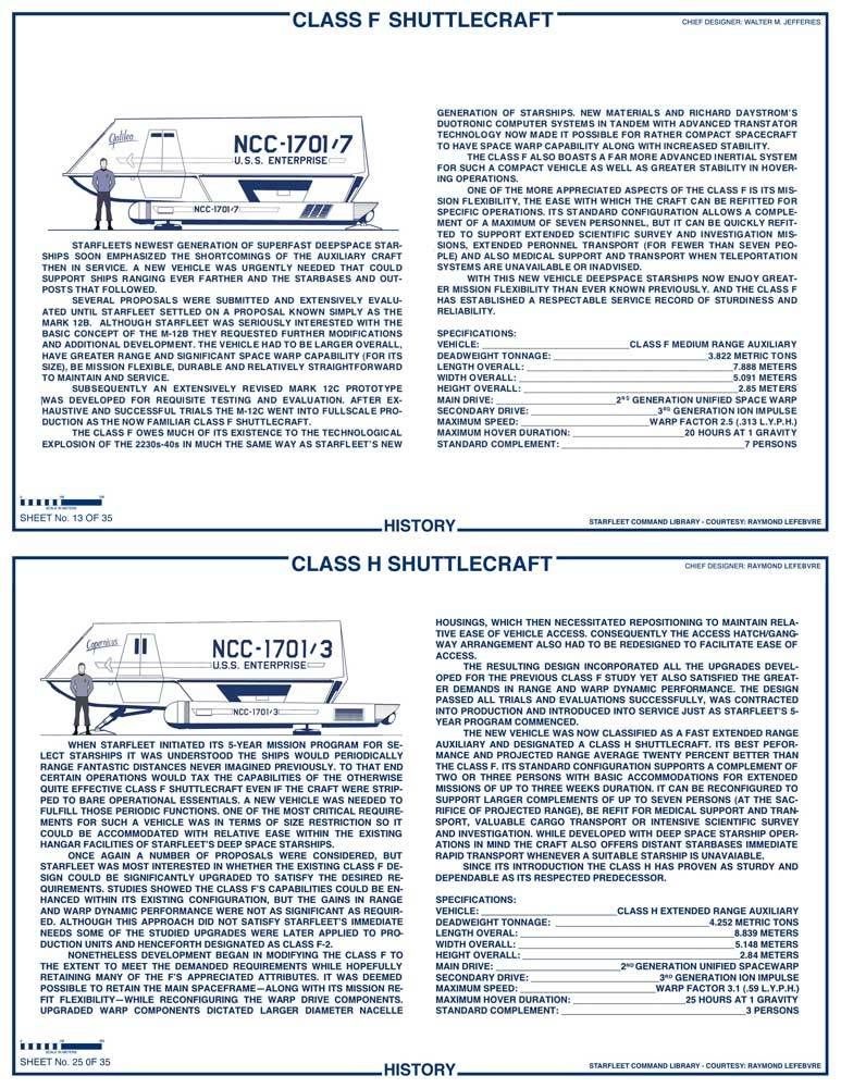
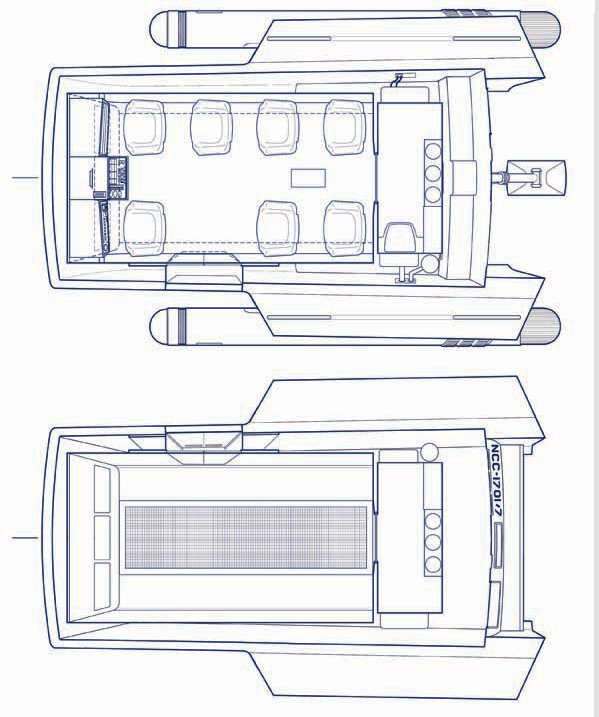
On the deck and ceiling plans above as well as the Class F cross sections you can see the beginnings of my thought process. A small panel at the aft of the craft was something of a jettison port for a small antimatter bottle. When the Galileo hit the Murasaki 312 phenomena and then plunged into the atmosphere of Tarsus II then a safety system automatically jettisoned the antimatter bottle since it somehow posed an immediate threat to the craft. Now the ship had very little fuel reserve apparently (energy) and so Scotty resorted to using energy drained from the hand phasers even though it wouldn't go far.
On the deck plan you can see I've made connections to small panels on each side of the ship beneath the stabilizers. One panel is an external electrical power hookup for powering various equipment during landed expeditions. The other is for draining waste matter as well as replenishing water and raw matter for the craft's basic replication/processing system.
If I can manage it I also envision having a limited number of EV suits stored between hulls for emergencies. These could be more simplified and basic versions of the full EV suits we've already seen onscreen.
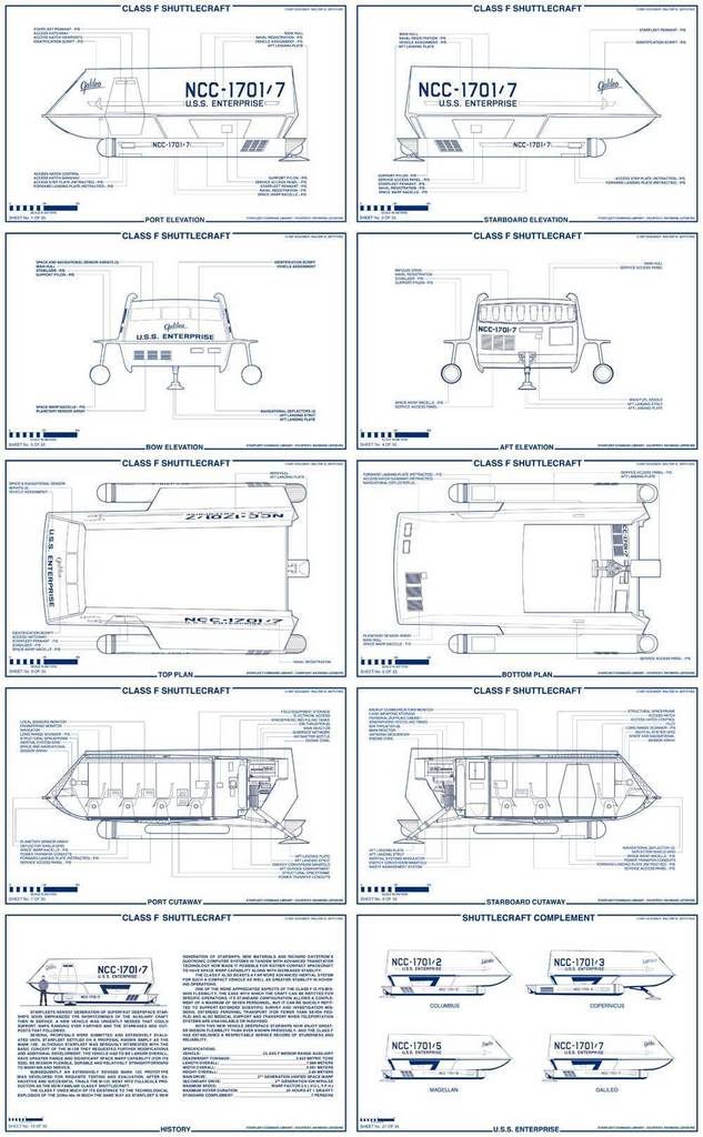
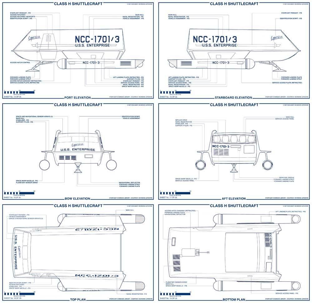
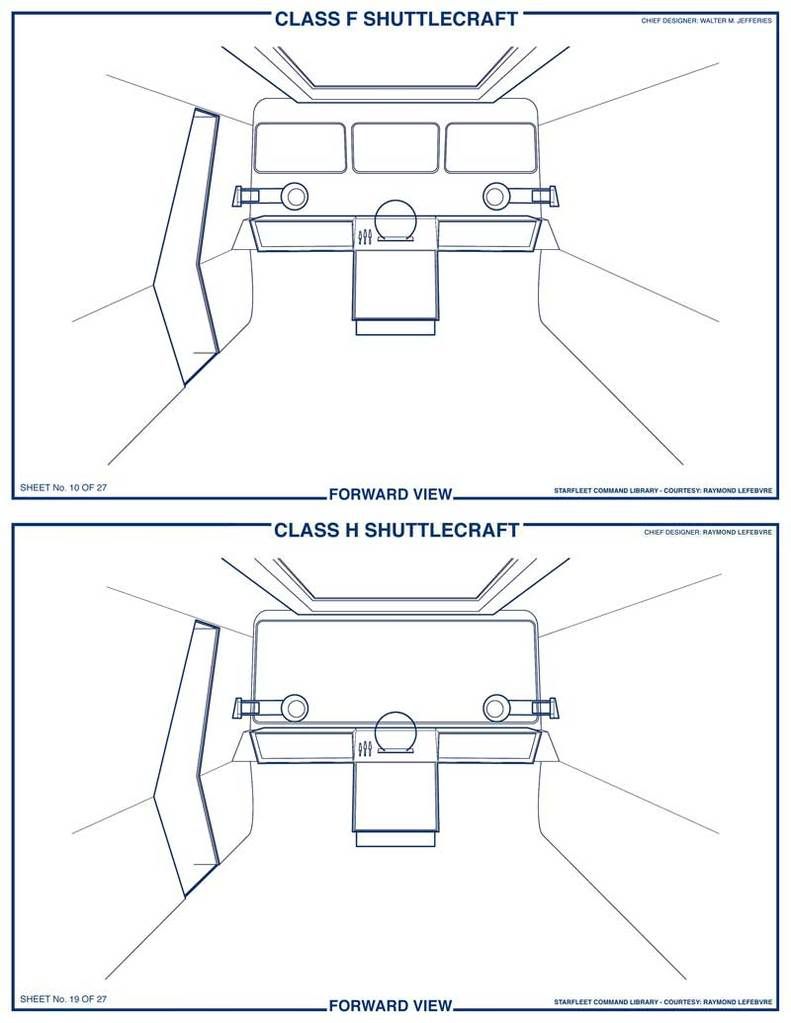
Although the Class F is supposed to offer a flexible refitted interior (as we've seen onscreen) I've chosen to stick with the familiar seven person setup as standard and eschew depicting differing interior configurations. However, I will draw the Class H's interior to reflect something of what we saw in TAS' "The Slaver Weapon." It will have three forward seats (like the Class F), but of slightly different design with a higher back. The aft part of the main compartment will likely have a storage cabinet, two fold-out bunks, a work table and possibly a "computer like" cabinet similar to one of the ones seen in "The Immunity Syndrome." The idea is to convey a vehicle meant for long range exursions even though the interior could be reconfigured easily much like the Class F.
Whaddya think?
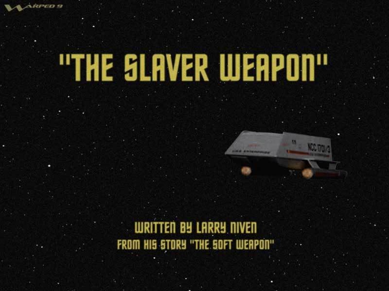
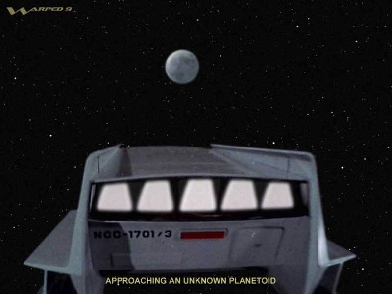
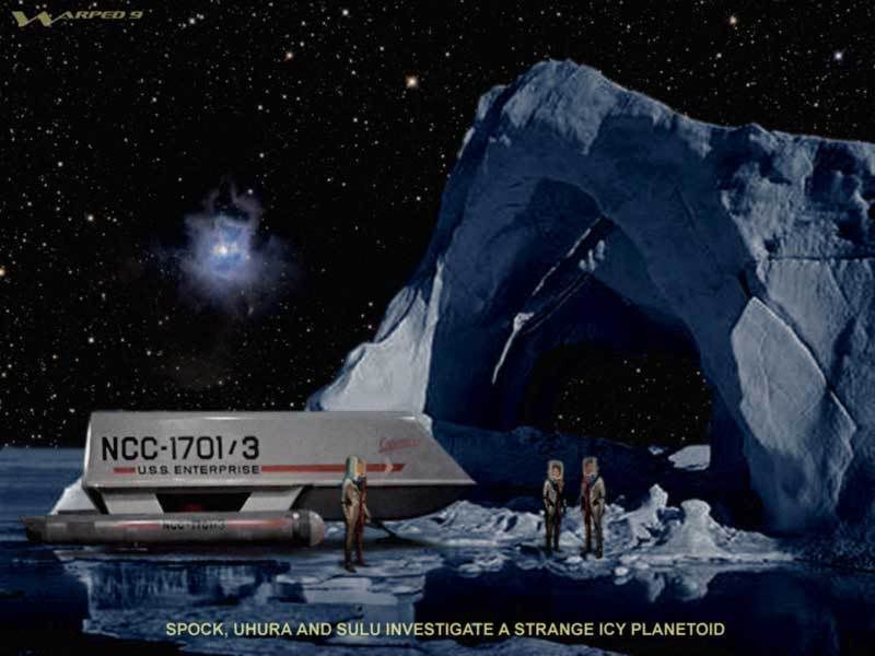
Here's a little revisit of some "live-action" versions of scenes from "The Slaver Weapon."
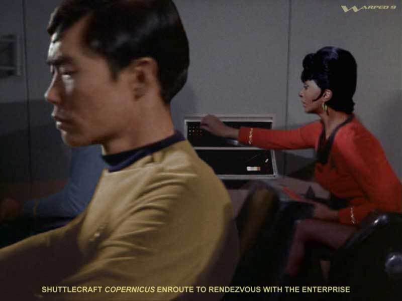
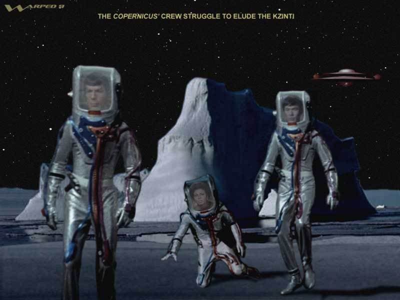
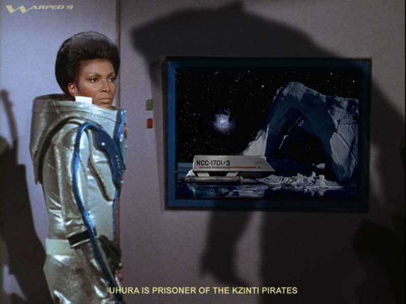
I'll be ther first to point out one big inconsistency in the pics above: Uhura is sporting three different hairstyles: One is from first season, one from second and two of the images have her with a third season style. Hey. I was stuck trying to find appropriate angles and expressions for the pics.
^^ Thanks guys. I must say that as I worked on this I did consider it in a larger context than just replicating what was seen onscreen. I tried to envision how it all fit together, and that goes way back to when I first considered how to make TOS' depiction of warp spaceflight more credibly consistent (even if not perfectly consistent) with the various references onscreen.
I see this proceeding in two steps essentially. Step 1: involves the interior detailing of the Class F (pretty much done) and the Class H (envisioned but not thoroughly established) and, Step 2: creating the structural spaceframe while considering what mechanicals will go in there.
On the deck and ceiling plans above as well as the Class F cross sections you can see the beginnings of my thought process. A small panel at the aft of the craft was something of a jettison port for a small antimatter bottle. When the Galileo hit the Murasaki 312 phenomena and then plunged into the atmosphere of Tarsus II then a safety system automatically jettisoned the antimatter bottle since it somehow posed an immediate threat to the craft. Now the ship had very little fuel reserve apparently (energy) and so Scotty resorted to using energy drained from the hand phasers even though it wouldn't go far.
On the deck plan you can see I've made connections to small panels on each side of the ship beneath the stabilizers. One panel is an external electrical power hookup for powering various equipment during landed expeditions. The other is for draining waste matter as well as replenishing water and raw matter for the craft's basic replication/processing system.
If I can manage it I also envision having a limited number of EV suits stored between hulls for emergencies. These could be more simplified and basic versions of the full EV suits we've already seen onscreen.
Although the Class F is supposed to offer a flexible refitted interior (as we've seen onscreen) I've chosen to stick with the familiar seven person setup as standard and eschew depicting differing interior configurations. However, I will draw the Class H's interior to reflect something of what we saw in TAS' "The Slaver Weapon." It will have three forward seats (like the Class F), but of slightly different design with a higher back. The aft part of the main compartment will likely have a storage cabinet, two fold-out bunks, a work table and possibly a "computer like" cabinet similar to one of the ones seen in "The Immunity Syndrome." The idea is to convey a vehicle meant for long range exursions even though the interior could be reconfigured easily much like the Class F.
Whaddya think?
Here's a little revisit of some "live-action" versions of scenes from "The Slaver Weapon."
I'll be ther first to point out one big inconsistency in the pics above: Uhura is sporting three different hairstyles: One is from first season, one from second and two of the images have her with a third season style. Hey. I was stuck trying to find appropriate angles and expressions for the pics.
Last edited:
Re: My TOS shuttelcraft (continued)...
All right, folks, bear with me here.
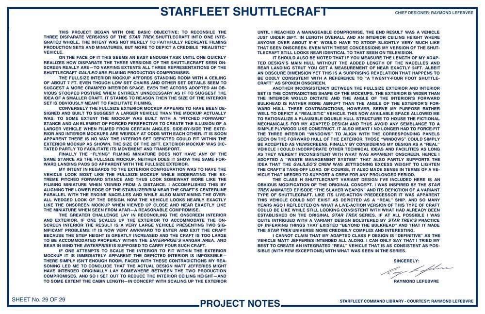
There is a tiny voice in the back of my head lamenting, “Why in hell did I ever try to undertake this?” By “this” the voice is referring to trying to depict the between hulls mechanical guts of the shuttlecraft. Why didn’t I just grey those sections out and label them as “classified” like Franz Joseph did in his Star Fleet Technical Manual? Well, I felt ambitious and challenged by the idea that this would put my drawings on another level and offer a degree of realism not often seen in illustrations of SF hardware.
Nevertheless I feel committed to doing it as planned, but I feel forced to backtrack a little because I’m not wholly satisfied with my cross sections to date. I’m content for the most part with what I’ve fashioned in the aft section, but the rest forward of that leaves me somewhat disappointed. To that end I feel compelled to start again with a partially clean sheet. By partially I mean I’m going to keep what I’ve rendered in regards to the cabin layout and detail as well as the stuff aft of the cabin (the impulse drive and assorted mechanicals in that section), but forward of that I need to start again.
Here is my reasoning:
Firstly I’ll begin by drawing up the life shell or inner hull. This will be what the ship looks like stripped of outer hull and structural framework or spaceframe as I like to call it. This will be, effectively, a viable lifeboat or life sustainable spacecraft except that it lacks any means of propulsion. It has sufficient power to sustain life support, communications, limited sensors and computer systems yet that power would be wholly insufficient to power any drive systems. This seems somewhat consistent with Scotty’s assertion that the “batteries” would be insufficient to power the ship for lift-off.
Next I’ll render the spaceframe that will provide additional structural support for the life shell as will as serve for the supporting framework for the outer hull. The spaceframe is also what many of the guts aftwards as well as the impulse drive are attached to.
What this process will do is give me a much better idea of what should be visible between hulls in my cross sections as well as deck and ceiling plans. I see this as rather painstaking, but I also think that if you’re going to do something then it’s worth doing right to the best of one’s ability.
For the most part I have to do this only once because there will be little variation between the innards of the Class F and H ships so I can pretty well just cut and paste the detailing over. But there are some differences:
- the Class H has five large ion thrusters as opposed to the F’s eight smaller ones.
- the Class H has one large interactive viewscreen as opposed to the F’s three smaller ones.
- the Class H’s gangway swings further down to the ground with fold out steps as opposed to the F’s gangway lowering onto its port nacelle.
- the Class H has one larger navigational deflector as opposed the F’s two smaller ones.
Once this project is complete I hope to go on to rendering other Star Trek projects, but I hasten to emphasize that I seriously doubt I’ll ever get this detailed with those. I’m particularly keen an tackling the TAS shuttlecraft, a Pike era shuttlecraft and the Pike era E.
The Pike era shuttlecraft could actually be done in concert with the E because it could be part of something like a Cage era reference manual, including uniforms which are something I already have drawn up from some years ago. I have something of a fascination with the Pike era E with its larger bridge dome, spiked engine domes and distinctive looking bridge. I’ve even toyed with the vague idea of rendering a Pike era E as if it were being done today, although it would be far removed from what’s been glimpsed for Trek XI and more evocative of the original design. But one thing at a time.
Just a thought.
All right, folks, bear with me here.
There is a tiny voice in the back of my head lamenting, “Why in hell did I ever try to undertake this?” By “this” the voice is referring to trying to depict the between hulls mechanical guts of the shuttlecraft. Why didn’t I just grey those sections out and label them as “classified” like Franz Joseph did in his Star Fleet Technical Manual? Well, I felt ambitious and challenged by the idea that this would put my drawings on another level and offer a degree of realism not often seen in illustrations of SF hardware.
Nevertheless I feel committed to doing it as planned, but I feel forced to backtrack a little because I’m not wholly satisfied with my cross sections to date. I’m content for the most part with what I’ve fashioned in the aft section, but the rest forward of that leaves me somewhat disappointed. To that end I feel compelled to start again with a partially clean sheet. By partially I mean I’m going to keep what I’ve rendered in regards to the cabin layout and detail as well as the stuff aft of the cabin (the impulse drive and assorted mechanicals in that section), but forward of that I need to start again.
Here is my reasoning:
Firstly I’ll begin by drawing up the life shell or inner hull. This will be what the ship looks like stripped of outer hull and structural framework or spaceframe as I like to call it. This will be, effectively, a viable lifeboat or life sustainable spacecraft except that it lacks any means of propulsion. It has sufficient power to sustain life support, communications, limited sensors and computer systems yet that power would be wholly insufficient to power any drive systems. This seems somewhat consistent with Scotty’s assertion that the “batteries” would be insufficient to power the ship for lift-off.
Next I’ll render the spaceframe that will provide additional structural support for the life shell as will as serve for the supporting framework for the outer hull. The spaceframe is also what many of the guts aftwards as well as the impulse drive are attached to.
What this process will do is give me a much better idea of what should be visible between hulls in my cross sections as well as deck and ceiling plans. I see this as rather painstaking, but I also think that if you’re going to do something then it’s worth doing right to the best of one’s ability.
For the most part I have to do this only once because there will be little variation between the innards of the Class F and H ships so I can pretty well just cut and paste the detailing over. But there are some differences:
- the Class H has five large ion thrusters as opposed to the F’s eight smaller ones.
- the Class H has one large interactive viewscreen as opposed to the F’s three smaller ones.
- the Class H’s gangway swings further down to the ground with fold out steps as opposed to the F’s gangway lowering onto its port nacelle.
- the Class H has one larger navigational deflector as opposed the F’s two smaller ones.
Once this project is complete I hope to go on to rendering other Star Trek projects, but I hasten to emphasize that I seriously doubt I’ll ever get this detailed with those. I’m particularly keen an tackling the TAS shuttlecraft, a Pike era shuttlecraft and the Pike era E.
The Pike era shuttlecraft could actually be done in concert with the E because it could be part of something like a Cage era reference manual, including uniforms which are something I already have drawn up from some years ago. I have something of a fascination with the Pike era E with its larger bridge dome, spiked engine domes and distinctive looking bridge. I’ve even toyed with the vague idea of rendering a Pike era E as if it were being done today, although it would be far removed from what’s been glimpsed for Trek XI and more evocative of the original design. But one thing at a time.
Just a thought.
Similar threads
If you are not already a member then please register an account and join in the discussion!