-
Welcome! The TrekBBS is the number one place to chat about Star Trek with like-minded fans.
If you are not already a member then please register an account and join in the discussion!
You are using an out of date browser. It may not display this or other websites correctly.
You should upgrade or use an alternative browser.
You should upgrade or use an alternative browser.
BLSSDWLF's TOS Enterprise WIP
- Thread starter blssdwlf
- Start date
Theres a small one for TUC?
or do you mean that partial bit used on TWOK and TUC?
According to Mutara.net's coverage of the Christie's auction there was a small Ent-A.
I suppose it doesn't matter which movie but it made it onto film.
This page has some images that might also be useful (also has links to two other pages of photos):
http://www.modelermagic.com/?p=16470
There are still images up of the studio model at Christie's as well:
http://www.mutara.net/Christies/EnterpriseA.html
Fair warning: most of these images are huge (which is why I didn't link to any directly)
These images are
 . With that wealth of image detail it should be possible for an able CGI artist to render an orthographic reproduction with optimal accuracy. Of course it would be great if there were a possibility to scan-measure the original VFX model, but somehow I don't see that happening unless the owner is known and agrees to such an enterprise.
This leaves us little choice than to use pictures to arrive at estimates and approximations.
^^ Because the saucer is too close to the viewer / camera the proportions are distorted and the widest part / diameter of the saucer is "hidden" from our view. However, the greater the distance from the viewer / camera the distortion effect becomes increasingly less, enabling a comparison of two objects close to one another.
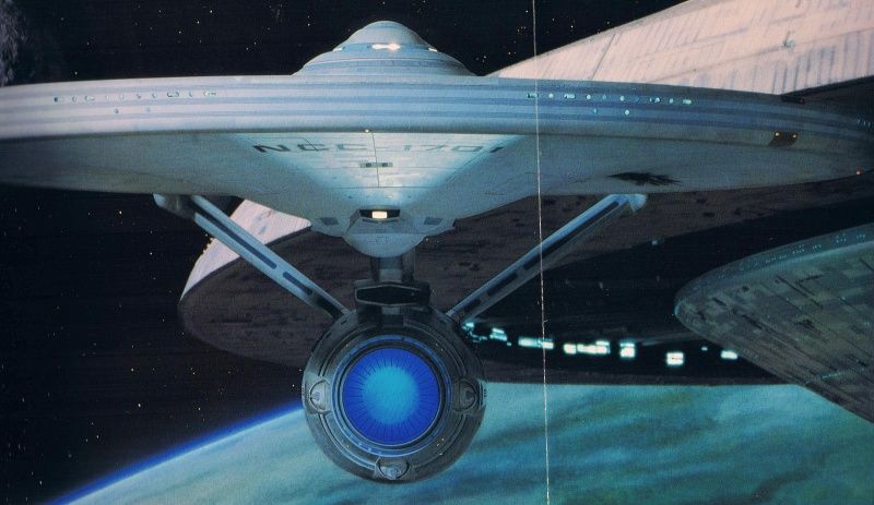
The same applies for the stern view shot, now in color, taken from my European TMP Promotion Portfolio:
There's obviously quite some distortion because of the camera lens used. Does it make the shot useless? No, because we are only interested in measuring the width of the impulse engines in relation to the width of the adjacent dorsal. If there would be a distorting effect stretching the impulse engines horizontally it would equally stretch the width of the dorsal.
However, given the diagonal nature of the dorsal and a slight distortion the further we move from the impulse engines away (because the bottom part of the dorsal is closer to us than the impulse engines) it's not possible to get exact measurements but a decent approximation / estimate.
The best front view shot of the VFX model I've thus far seen is this one: http://www.modelermagic.com/wordpress/wp-content/uploads/2009/09/KG_MD_UK1998_1701-A-050.jpg
(again, the widest part of the dorsal is further behind and partially obscured by the front torpedo view)
To get a better approximation we should also pay attention to this shot, from the other source: http://www.mutara.net/Christies/detail models/Enterprise A/IMG_2044.JPG
and then consider this:
My first instinct tho is that the neck, like an airplane wing, looks thinner than it actually is...
I assume all of us have not grown up surrounded exclusively by trees and caves but surrounded by rectangular buildings, towers, vehicles and so on.
Consciously or subconsciously we measure distances and proportions of objects on a daily basis with "instinct" and most of us have gotten rather good at this based on practical experience.
So while a ruler or a computer can be a powerful ally to make the necessary dorsal width calculations, it does not replace this kind of experience.
Bob
However, the greater the distance from the viewer / camera the distortion effect becomes increasingly less, enabling a comparison of two objects close to one another.
The same applies for the stern view shot, now in color, taken from my European TMP Promotion Portfolio:
...
So while a ruler or a computer can be a powerful ally to make the necessary dorsal width calculations, it does not replace this kind of experience.
Since you're still fixated on using photos to make your measurements, then consider reading up on distance, perspective, field of view and focal length. None of the photos and screenshots available flatten the features of the ship because they're simply shot too close.
Just from both photo and 3D experience I can tell you that your visual estimates do not replace a good orthographic view of one such as the CG TMP DE version done by FI.
^ the DE model isn't extremely accurate tho (great for SD in 2001.)
One example:
Notice the extreme hump on the TB superstructure and the horizontal top and up-sloped bottom of the "photon exhaust" in the image in this post (compare to seam above as well as deck lines you overlayed.)
Now compare that to this image from TWOK.
Notice that the "photon exhaust" top is not parallel to the seam (declination in the cut going forward) but the bottom is. Some thing that bears up when examining the studio model (large image).
So IMO not a great standard and not one to be used to make accurate statements about the refit Enterprise.
BK613 beat me to it. Yes, the banana curved torpedo bay "roof" of the DE CGI model is one of the worst offenders, IMHO.
One can also spot other inaccuracies comparing the image segment of the DE CGI with the actual VFX model:

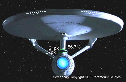
IMHO, the above picture (courtesy ILM-The Art of Special Effects) has wiggle room estimating the width of the dorsal (due to the ovoid nature of the dorsal).
The observed width of the dorsal in the TUC screencap follows the same rules that have been known since the Renaissance: An object (here: dorsal) behind another object (here: front of torpedo bay) will always appear smaller than it actually is in real life.
The way I see it the guys doing the DE CGI rendering didn't really take this into account. But unless I'm mistaken their CGI refit Enterprise was mostly used for long-distance shots, so it probably didn't require that much accuracy.
Bob
One can also spot other inaccuracies comparing the image segment of the DE CGI with the actual VFX model:
IMHO, the above picture (courtesy ILM-The Art of Special Effects) has wiggle room estimating the width of the dorsal (due to the ovoid nature of the dorsal).
The observed width of the dorsal in the TUC screencap follows the same rules that have been known since the Renaissance: An object (here: dorsal) behind another object (here: front of torpedo bay) will always appear smaller than it actually is in real life.
The way I see it the guys doing the DE CGI rendering didn't really take this into account. But unless I'm mistaken their CGI refit Enterprise was mostly used for long-distance shots, so it probably didn't require that much accuracy.
Bob
Gary Kerr took physical measurements of the model and translated them into a set of plans back in 2005. I thought that a lot of that information was publicly available, but I don't seem to find any place that has it so I might be wrong about that. Kerr tends to not share a lot of this stuff openly, and if he doesn't want this in the public domain, then it most likely isn't.This may sound equally dumb, but is there a definitive source for the official measurements?
Using the information I have I cross checked these plans against the measurements of the studio model, and they seem spot on. So these would be a better alternative to any other plans of the TMP Enterprise (if the actual studio model is what you want to use as a foundation).
Well judging by the storm which has apparently blown up around big Jim, it seems likely that these are indeed Kerr's plans.
Thanks for checking Shaw, I had originally thought that the Engineering Docking Port had been placed too high on Big Jim's plans, but it seems that Drexler's might have actually placed it too low!
Thanks for checking Shaw, I had originally thought that the Engineering Docking Port had been placed too high on Big Jim's plans, but it seems that Drexler's might have actually placed it too low!
Actually, I don't think those plans are accurate, either. Here's why.
According to the plans the widest portion of the torpedo deck is the very front, but in photos from head-on you can see that that isn't the case, otherwise the very front of the assembly would always be visibly wider that what's behind it, and it ain't.
According to the plans the widest portion of the torpedo deck is the very front, but in photos from head-on you can see that that isn't the case, otherwise the very front of the assembly would always be visibly wider that what's behind it, and it ain't.
^ the DE model isn't extremely accurate tho (great for SD in 2001.)
One example:
Notice the extreme hump on the TB superstructure and the horizontal top and up-sloped bottom of the "photon exhaust" in the image in this post (compare to seam above as well as deck lines you overlayed.)
Yes, I've acknowledged in a previous post that the TB section has some inaccuracies.
Now compare that to this image from TWOK.
Notice that the "photon exhaust" top is not parallel to the seam (declination in the cut going forward) but the bottom is. Some thing that bears up when examining the studio model (large image).
So IMO not a great standard and not one to be used to make accurate statements about the refit Enterprise.
I only partially agree with you.
IMO, this CG model is in orthographic view and as you noted, appeared in the DE film. We can make an accurate statement about this CG Enterprise as a representative of the refit Enterprise whereas we cannot make such a claim of the perspective-distorted photos and screen captures.
Gary Kerr took physical measurements of the model and translated them into a set of plans back in 2005. I thought that a lot of that information was publicly available, but I don't seem to find any place that has it so I might be wrong about that. Kerr tends to not share a lot of this stuff openly, and if he doesn't want this in the public domain, then it most likely isn't.This may sound equally dumb, but is there a definitive source for the official measurements?
Thanks Shaw for checking but yeah, Kerr's data isn't publicly available.
Using the information I have I cross checked these plans against the measurements of the studio model, and they seem spot on. So these would be a better alternative to any other plans of the TMP Enterprise (if the actual studio model is what you want to use as a foundation).
Do you mind sharing what Kerr's measurements were on the Torpedo Bay and Dorsal? It's an interesting curve and it would be helpful to know where he measured the width and if he made multiple width measurements spanning the length of the torpedo bay and dorsal.
Well judging by the storm which has apparently blown up around big Jim, it seems likely that these are indeed Kerr's plans.
Thanks for checking Shaw, I had originally thought that the Engineering Docking Port had been placed too high on Big Jim's plans, but it seems that Drexler's might have actually placed it too low!
Thanks for spotting the thread. There are some oddities like the botanical windows on the engineering hull not curving with the hull line above it and the docking port does feel a little too high as well. I'd have to give it a good comparison check to see how accurate it is.
Actually, I don't think those plans are accurate, either. Here's why.
According to the plans the widest portion of the torpedo deck is the very front, but in photos from head-on you can see that that isn't the case, otherwise the very front of the assembly would always be visibly wider that what's behind it, and it ain't.
Yes, I noticed that too. I'm hoping Shaw might have more details on how that section was measured.
According to the plans the widest portion of the torpedo deck is the very front, but in photos from head-on you can see that that isn't the case, otherwise the very front of the assembly would always be visibly wider that what's behind it, and it ain't.
Yes, there is some "relief" as the torpedo bay housing gets to the launchers, that's equally absent in the David Kimble blueprints (and exagerrated in the DE CGI Version, IMO).
Also, the placement of the dorsal windows is idealized. We can see in a couple of screenshots that there is space between the upper and the two lower window rows.
Almost seems to me that it's easy to research which set of earlier blueprints provided the base to make the necessary modifications and corrections.
")
Frankly, after what I had seen before, I'm nevertheless very impressed with these orthographic blueprints which look to me like the best currently available (thanks Shaw for the heads-up).

Back to the issue of this thread, I found the top view of the engineering hull very interesting, where the dorsal's stern is wider than the bow, which is apparently correct.
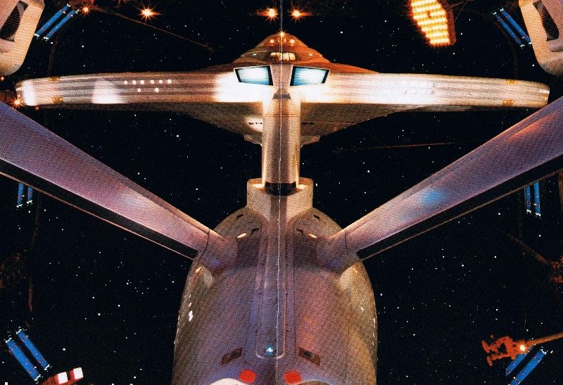
This looks like a good opportunity to highlight this screencap from TMP. Originally, I had always thought that the external cover plates for the "impulse shaft" looked curved because of a camera lens distortion.
But since we are are looking at a diagonal shape the widest part of dorsal will slowly but surely "wander" from the top down towards the stern, so the forward area of the dorsal is relieved on its way down which results in what I had erroneously assumed to be a distortion.
Bob
According to the plans the widest portion of the torpedo deck is the very front, but in photos from head-on you can see that that isn't the case, otherwise the very front of the assembly would always be visibly wider that what's behind it, and it ain't.
Yes, there is some "relief" as the torpedo bay housing gets to the launchers, that's equally absent in the David Kimble blueprints (and exagerrated in the DE CGI Version, IMO).
Also, the placement of the dorsal windows is idealized. We can see in a couple of screenshots that there is space between the upper and the two lower window rows.
Almost seems to me that it's easy to research which set of earlier blueprints provided the base to make the necessary modifications and corrections.
It'd be easier to know at what points on the physical ship the measurements were made so we can determine how far off the inaccuracies are to make the corrections.
Back to the issue of this thread, I found the top view of the engineering hull very interesting, where the dorsal's stern is wider than the bow, which is apparently correct.
You should look at Slice #2 on the dorsal as the dorsal's stern at the base is about the same width as the bow. Are you looking at Slice #1 where the "torpedo vent" has been omitted thinking that the dorsal stern (at the base) is wider than the bow?
BTW, I did a quick measurement on Slade's plans, using the forward/stern view and the torpedo bay is 114px wide and the saucer is 1345px wide. Multiply that against 467.5' wide for the ship (assuming a 1,000' ship) and the torpedo bay is 39.6' wide in Slade's version. It's about 7' narrower than the DE version.
Not the only area with inaccuracies. Other changes include flattened complex surfaces (like the top of the TB bay and on the lower sensor dome "boxes"), window placement, and structural shapes (like the 3 protrusions around the deflector dish.) And I use the word changes here because some variations could be deliberate. Not hard to imagine the desire to reduce polygons so the rendering times could be increased on that turn-of-the-century technology LOL.^ the DE model isn't extremely accurate tho (great for SD in 2001.)
One example:
Notice the extreme hump on the TB superstructure and the horizontal top and up-sloped bottom of the "photon exhaust" in the image in this post (compare to seam above as well as deck lines you overlayed.)
Yes, I've acknowledged in a previous post that the TB section has some inaccuracies.
And I don't have a problem with that. This place would be boring if we all agreed LOL. Seriously though, I come here to exchange ideas and see different perspectives, not litigate differences of opinion.I only partially agree with you.
And normally I would agree with you about the value of orthos, if this CG model was a decent representation of the primary filming model. IMO, it is not and using it (to me anyway) is akin to using the AMT model to make judgments about the TOS filming model.IMO, this CG model is in orthographic view and as you noted, appeared in the DE film. We can make an accurate statement about this CG Enterprise as a representative of the refit Enterprise whereas we cannot make such a claim of the perspective-distorted photos and screen captures.
(and FWIW the front and back views are not true orthos; you can see the effects of perspective on the engines.)
The question then is did they alter the width of the torpedo bay and dorsal sections in their quest to cut back on polys.Not the only area with inaccuracies. Other changes include flattened complex surfaces (like the top of the TB bay and on the lower sensor dome "boxes"), window placement, and structural shapes (like the 3 protrusions around the deflector dish.) And I use the word changes here because some variations could be deliberate. Not hard to imagine the desire to reduce polygons so the rendering times could be increased on that turn-of-the-century technology LOL.^ the DE model isn't extremely accurate tho (great for SD in 2001.)
One example:
Notice the extreme hump on the TB superstructure and the horizontal top and up-sloped bottom of the "photon exhaust" in the image in this post (compare to seam above as well as deck lines you overlayed.)
Yes, I've acknowledged in a previous post that the TB section has some inaccuracies.
And I don't have a problem with that. This place would be boring if we all agreed LOL. Seriously though, I come here to exchange ideas and see different perspectives, not litigate differences of opinion.I only partially agree with you.And normally I would agree with you about the value of orthos, if this CG model was a decent representation of the primary filming model. IMO, it is not and using it (to me anyway) is akin to using the AMT model to make judgments about the TOS filming model.IMO, this CG model is in orthographic view and as you noted, appeared in the DE film. We can make an accurate statement about this CG Enterprise as a representative of the refit Enterprise whereas we cannot make such a claim of the perspective-distorted photos and screen captures.
Since it was used as a stand-in for the TMP filming miniature it does have more weight than say an AMT model that never stood in for the 11' TOS miniature.
Although you don't sound like you want to get into a litigating conversation then I'll leave it at this:
1. We can get the max width of the torpedo bay and dorsal for the CGI DE version.
2. We cannot get the max width for the filmed version with the forward and stern photo views.
3. We do not know at this time where and what measurements were made of the filmed model as presented by the Jim Slade or Gary Kerr blueprints.
(and FWIW the front and back views are not true orthos; you can see the effects of perspective on the engines.)
Can you point this out graphically? There is an odd thing on the interior facing parts of the nacelles from the stern view but that appears more of a photoshop/editing issue than a perspective problem.
Edit: Just for clarification: I'm not saying the DE Enterprise is the defacto version of the TMP filming miniature to go by. I'm saying that it's the only one that we have an ortho for that also was onscreen. Until there is some definitive measurements of the TMP filming miniature of the torpedo bay and dorsal and where the points were measured then there is nothing better to go on, IMO.
Last edited:
From the front the vertical stem of the "cross" does not align with the center of the top crystal; likewise, the vertical stern detail also doesn't align with the center of the top crystal (and you can see a bit more of the interior of the nacelle.)(and FWIW the front and back views are not true orthos; you can see the effects of perspective on the engines.)
Can you point this out graphically? There is an odd thing on the interior facing parts of the nacelles from the stern view but that appears more of a photoshop/editing issue than a perspective problem.
I just took a look and you're right. It is shifted.
Well that's a bummer then as there are no good orthos at all. Who owns the auctioned refit miniature? We're going to need some measuring calipers and someone with a friendly personality to contact the owner
")
Similar threads
- Replies
- 482
- Views
- 65K
- Replies
- 13
- Views
- 4K
- Replies
- 87
- Views
- 22K
If you are not already a member then please register an account and join in the discussion!