How did you arrive at 1067 feet? I thought you were using 1080?
-
Welcome! The TrekBBS is the number one place to chat about Star Trek with like-minded fans.
If you are not already a member then please register an account and join in the discussion!
You are using an out of date browser. It may not display this or other websites correctly.
You should upgrade or use an alternative browser.
You should upgrade or use an alternative browser.
- Status
- Not open for further replies.
Go back and re-read my first post in the thread. I started off using 947'... and immediately ran into so many problems that I abandoned it and tried 1080', which worked pretty well. But as I fine-tuned things, I determined that the ideal length was actually 1067'. In fact, I'm still open to revising this further, though I can't imagine why I'd do so. Everything has worked out so perfectly at this scale so far that I think I've pretty much locked in on the new number.How did you arrive at 1067 feet? I thought you were using 1080?
The point of this exercise, after all, isn't "to prove one side right and the other wrong." It's to determine what the best possible "real life" configuration for the ship that I can come up with would be. And so far, 1067' is looking really, really good.
Make sense?
Now... a bit more progress this afternoon...
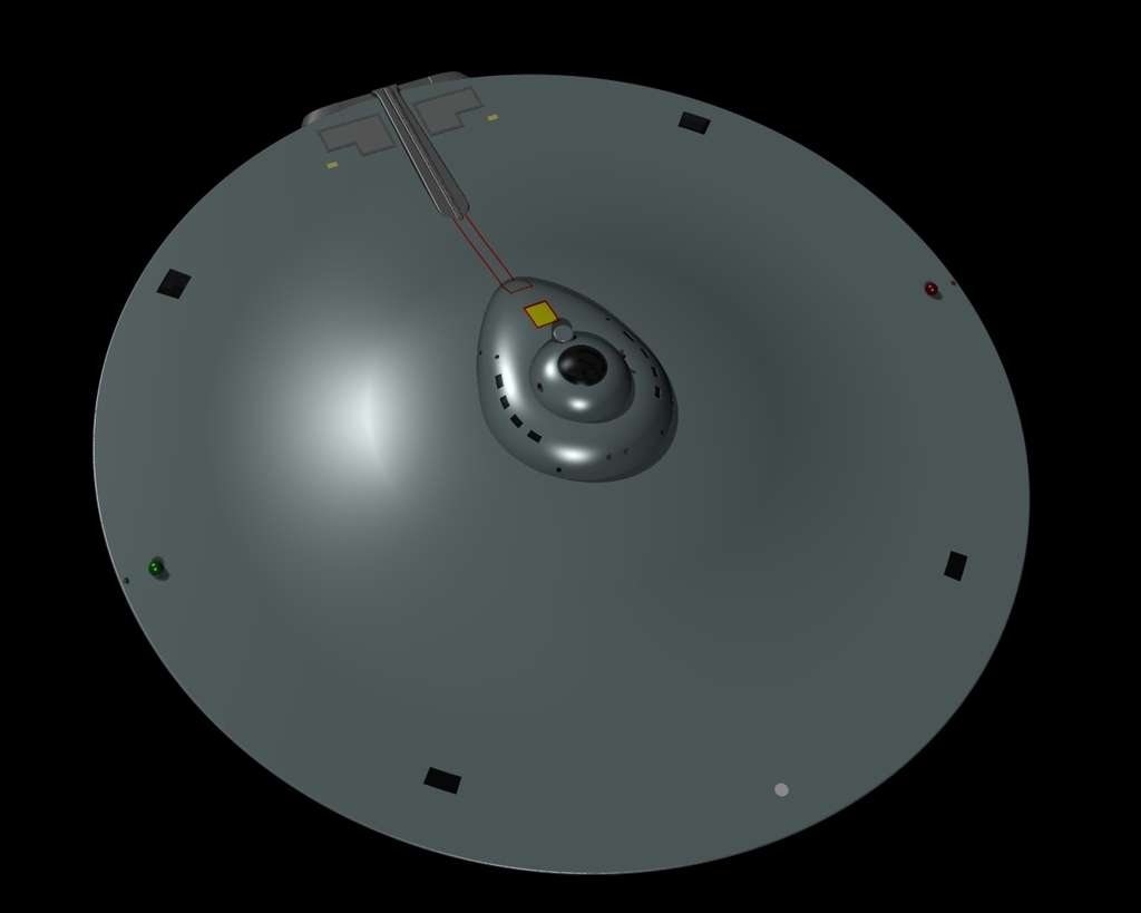
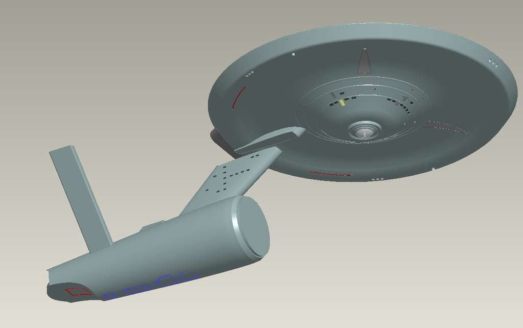
I've completed the last details on the top side. I might add in ship's ID markings later, but for now I'm leaving that off (and if I do, they will be the very last features in the model).
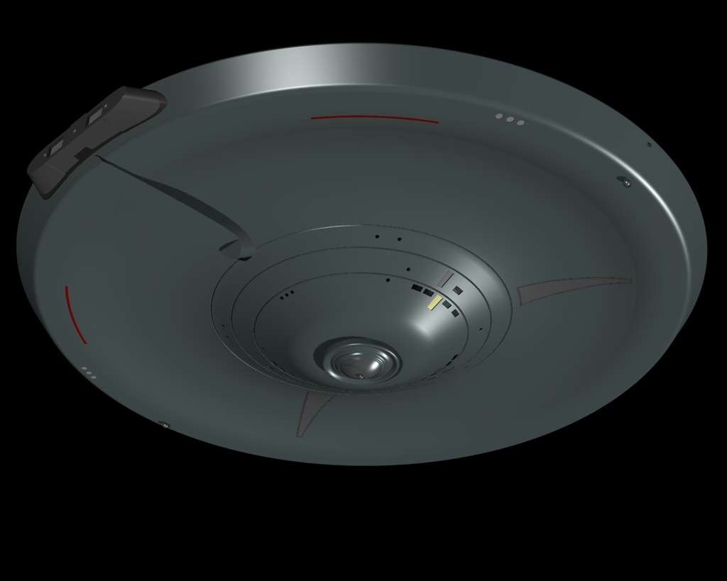
I still haven't done the rim windows or sensor portholes, but those are the sole remaining external features. Everything else is done. (No ship's ID markings down here either, for the same reason.)
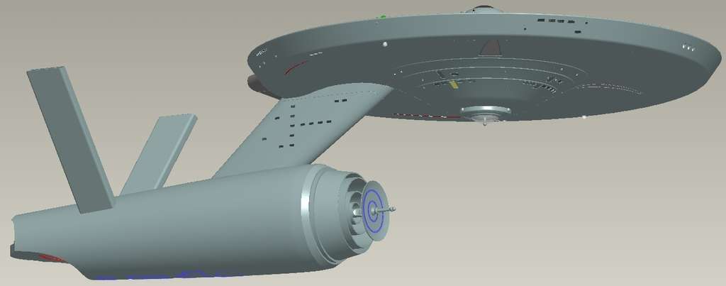
And a closer look at the separation. This is now, formally, an independent model!
")
I downsized a bit to make the bridge match up slightly better and to make the various decks line up slightly better with the local window locations.^^ Could you clarify why you consider 1067ft. ideal as opposed to 1080ft? I know it's only a difference of 13ft. but what was the determining factor rather than just take as much space as you can get to cram all the stuff in there?
Either can work, but based upon my efforts to make sets (or in the case of the bridge, McMaster's prints) match up with the various external drawing sets, I just ended up tweaking it up and down slightly until I converged on a "best fit."
Truthfully, I didn't even pay attention to length when I was doing this. I just tweaked the image scales up and down. Once I had everything lining up nicely, I created datum planes which represented the leading, trailing, pore and starboard edges of the primary hull, created datum planes representing the primary hull decklines, and representing the centerlines of the nacelles and secondary hull. (I actually ended up very slightly adjusting the secondary hull centerline later once I recognized that the axis of the secondary hull is at the exact convergence of the nacelle pylons by design... a key reason I decided to do the "pylons through" approach.)
It was only once I had the full thing worked out that I measured the distance from the nacelle trailing-edge datum plane to the saucer leading-edge datum plane. I had not measured this... at all... prior to that. The reason was that I didn't want preconceptions to guide my work. My entire purpose was to make the sets we know fit into the hull we know.
I actually expected the final number to be closer to 1080'. But that's not the number I arrived at, and I'm not going to try to "drive my results to meet my expectations." That's the sort of thing that bad scientists and bad engineers do.
I let the process give me my results, not vice-versa, in other words. Make sense?
I'm curious about how the shuttlebay fits in. I always wanted to see how big the ship would need to be if you took the width of the shuttle set piece and compared that to the width of the model shuttle photographed with the shuttle bay model and use those stills to arrive at a scale size for the shuttlebay if built to the same scale as the set piece shuttle. Then how big would the ship need to be to fit that inside it?
--Alex
--Alex
That's definitely one of the things that's always driven me towards the 1080' number in the past. You really can't fit the shuttlebay as shown on-screen with the 947' ship, in my opinion, regardless of whether or not you put it under the pylons or behind them.I'm curious about how the shuttlebay fits in. I always wanted to see how big the ship would need to be if you took the width of the shuttle set piece and compared that to the width of the model shuttle photographed with the shuttle bay model and use those stills to arrive at a scale size for the shuttlebay if built to the same scale as the set piece shuttle. Then how big would the ship need to be to fit that inside it?
--Alex
Well, I got sort of carried away today, and so I've accomplished my "big goal" for the weekend already.
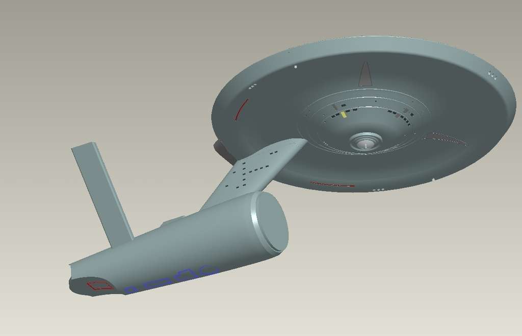
(I wouldn't have gone this far today, except that the secondary hull started collapsing when I tried to make it a separate model... and having problems like that pop up always grabs my full attention.)
One more picture before calling it a night.
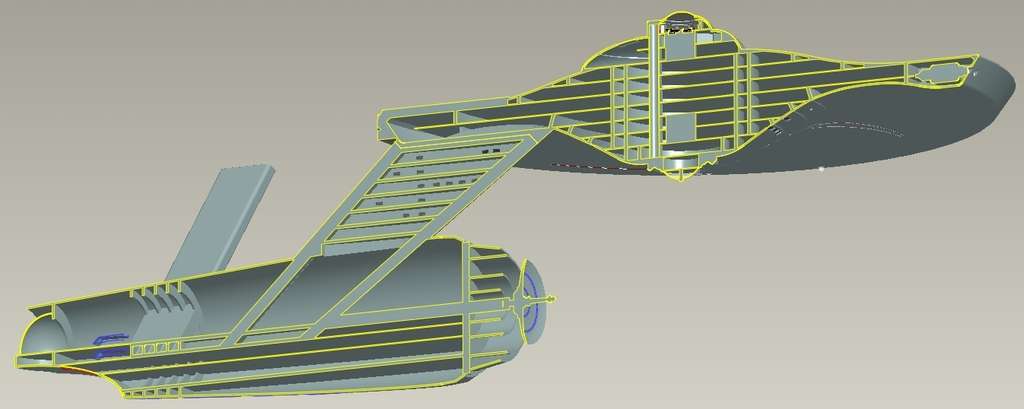
I decided to give the landing bay and hangar deck a quick once-over... It became necessary to tweak deck levels a bit more, but interestingly, Warped9's shuttle actually fits, IF I adjust the deck below to exactly match the hatch (I'd left some margin around the hatch previously).
Here's a side-view of the whole ship, in section. You can see the landing bay. Note that the bay itself does not run to the exterior hull. There's actually a fair amount of space between the two. This is well-established by the TOS filming minature of the deck, which clearly shows that the doors are significantly larger than the interior structural ring inboard from them... and when comparing the doors themselves (on the 11' model) to the opening in which they sit. I've only "eyeballed" the size of the opening in that aftmost bulkhead, so far. But I'll be doing a bit more analysis as I move forward.

very interesting and very nice work there 

That's not been lost on me (since I'm using meters as my default unit, and only talking "feet" because that's the nature of the conversation, normally, on this topic). Once I have everything worked out, I may do a comparison of 947'/1080'/1067', and the "refit" along with it.This is really great work. You're just a few inches over 325 meters (325.2216 to be exact). That number seems a bit less random than 1067'. How does the diameter of the saucer at 1067' compare to the one on the 1000 foot refit?
For now, I haven't done any "secondary hull" work today, and I'm done (only spending a few hours on it today).
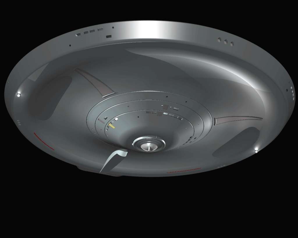
What I did today was finish the windows on the primary hull (turns out I found my second major error in Sinclair's prints, by the way... the first was that the upper running light locations aren't the same in all views, and this one is that the aft saucer rim windows aren't the same in the bottom and starboard views).
I also put in a couple of details I'd forgotten about (damn, why'd nobody remind me? What am I paying you guys for?
") ) Specifically, the three little "knobs" around the lower sensor platform, and the "rim" at the back of either of the triangular shapes. Both are there now, though.
) Specifically, the three little "knobs" around the lower sensor platform, and the "rim" at the back of either of the triangular shapes. Both are there now, though.The only external features I've been stewing about might be some subtle indications of RCS thrust ports (either covered or with a screen over them, so that we could accept that they wouldn't even be visible in 1966 TV terms), and slide-back hatches for the phaser and torpedo firing ports. I won't give any indication (externally) of my lifeboat positions, and while I've been thinking about a "gangway hatch" on the port side, behind a slide-panel, I've largely decided against it, though I could change my mind.
This time, with my renders, I put sources inside of the running lamps. It's not really surprising to see how it turns out, but it IS curious that we never saw any indication of this on-screen... we really ought to have, don't you think?
And... well... "festive," isn't it?
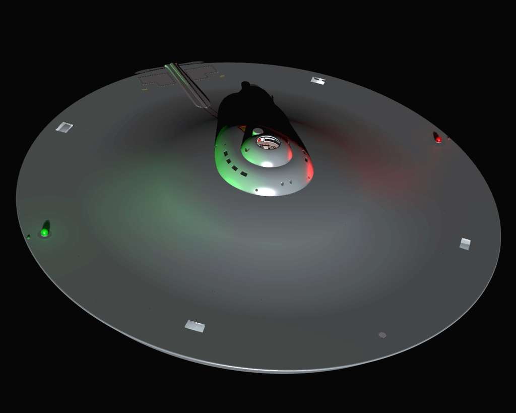
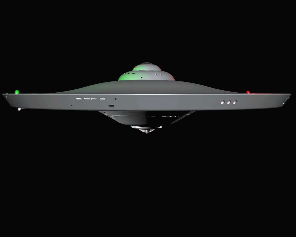
This time, with my renders, I put sources inside of the running lamps. It's not really surprising to see how it turns out, but it IS curious that we never saw any indication of this on-screen... we really ought to have, don't you think?
That depends. Do your light sources have falloff on them (e.g, are they decaying with the square of the distance)? If not, then the light hitting the bridge module going to look much, much brighter than it would in reality.
^^Also, how do you feel about strobes or slowly revolving 'siren' style running lights? One of the things I liked about the original FX for "Space Seed" was the way the starboard runnig light seem to revolve, sold the whole scene IMHO, but was sadly lacking in the remastered version.
Last edited:
Well, the add-on renderer I'm using here has "normal falloff" by default, though it can be tweaked. Basically, it's sort of like Christmas lights... the impact of the lights is greater when other light sources are at their minimum. I just through that it was interesting that we could never really see this (obviously studio lighting techniques, etc) while, if the ship were real, we certainly would see it, to some extent or another.This time, with my renders, I put sources inside of the running lamps. It's not really surprising to see how it turns out, but it IS curious that we never saw any indication of this on-screen... we really ought to have, don't you think?
That depends. Do your light sources have falloff on them (e.g, are they decaying with the square of the distance)? If not, then the light hitting the bridge module going to look much, much brighter than it would in reality.
Obviously, I picked things up and did a bit more... when I get onto a roll this is almost compulsive. Ah, well...
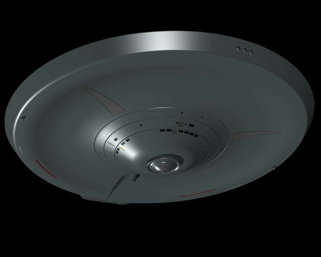
So, two final images for today. Mainly, this is showing the (nearly complete, except for the concentric rings) deflector/sensor dish. I never liked how FJ (and others) just have it "stuck" onto the front of the secondary hull, with no special support structure or anything. So... mine is separated by a massive "shield wall" to isolate the enormous energies from the dish from the inhabited areas... and the main "stem" of the dish actually is tied into the secondary hull's principal structural elements.
FYI, the lower regions of the secondary hull, below the hangar deck (remember, the hangar is the deck below the landing bay in my terminology!) will be cargo decks, though they may also have a pool and/or a bowling alley or something like that. Main engineering will be aft, with the "triangle" between the pylons and the control room forward of that, fairly high up. Other engineering spaces will surround the central structures. There will also be some habitation space down there, mainly along the outermost areas, adjacent to the hull. And the uppermost region, which isn't complete yet, will be the "strongback"... a lot of ribbing and trusswork, probably double-purposed as bulk storage space of some sort.
It's pretty cool that you're doing this in Pro-E, that's pretty much the only 3D program I'm any good at. Aside from some versions of CAD that are useless for doing art. Too bad I don't have Pro-E on my home computer.
I think one of the first things I did with my ENT model (the physical one I bought, not a CG one) was see what it looked like in the dark lit up. The entire upper saucer is bathed in red light from the nacelles and the bridge & sensor domes are like headlights, hard to look at directly, under those conditions. So if the ship were real and in deep space it would look pretty different.
I think one of the first things I did with my ENT model (the physical one I bought, not a CG one) was see what it looked like in the dark lit up. The entire upper saucer is bathed in red light from the nacelles and the bridge & sensor domes are like headlights, hard to look at directly, under those conditions. So if the ship were real and in deep space it would look pretty different.
Hey Cary, I may have missed this earlier in the thread, but are you positing that the three circular portholes on the bow of the saucer rim are sensors or weapons emplacements of some sort? I was admiring your latest cutaway just now and noticed what appeared to be some sort of machinery directly attached to the center port.
Hi, Prof...Hey Cary, I may have missed this earlier in the thread, but are you positing that the three circular portholes on the bow of the saucer rim are sensors or weapons emplacements of some sort? I was admiring your latest cutaway just now and noticed what appeared to be some sort of machinery directly attached to the center port.
Aw, you missed the entire "Nomad" exchange earlier. I did those details almost identical to "Nomad" in profile originally, but altered them a bit to make it a little less "cheesy." However, it was still caught by a couple of guys on here. Go back to the first page (about 3/4 down, I think?) and you'll see the entire conversation, including a description of what the details are.
However... "Cliffs' notes version... The TMP Enterprise had a "bright forward light" on the underside of the primary hull (part of an array of four, with another three on-top, around the bridge base). I always took these as active scanners (remember, scanners are like radar - active devices which send out energy and measure the returns. Sensors are passive - things like IR cameras and so forth.)
The "three ports" on the primary hull leading edge don't match up with anyone's eyeline. So I always took them as mechanical in nature rather than as "viewing windows." In fact, most of my "round portholes" are windows for detection hardware... while the rectangular ones are for people to look out of. (This lets you work on most of the the sensors and scanners while still inside the ship... very much in keeping with M.J's design philosophy.)
So what you see there are three high-powered "scanner telescopes" which are effectively the Enterprise's main "eyes" looking forward. Since they have to be able to tell the crew that they're about to run over a planet before they get to it, they've got to be pretty powerful (able to reach ahead by at least several minutes' worth of travel at maximum warp).
Cary, I'm so glad that your version of the deflector dish setup reflects the ring structure behind the dish. Like you, I always hated that FJ didn't acknowledge that. I know that Jefferies's cutaway drawing didn't show it, but as far as I'm concerned, if it's a part of the models it should be included.
I was thinking another reinforcing ring might be necessary along the line where the secondary hull 'folds' from the 45 degreeish angle to the more or less straight lines of the rest of the structure but she's your baby.
I was thinking another reinforcing ring might be necessary along the line where the secondary hull 'folds' from the 45 degreeish angle to the more or less straight lines of the rest of the structure but she's your baby.
- Status
- Not open for further replies.
Similar threads
If you are not already a member then please register an account and join in the discussion!