Jefferies and the Undercut
I'm putting this here as it has to do with Jefferies view of the Enterprise and the models as constructed under Datin's supervision, and next to nothing to do with Franz Joseph's work.
Before starting, and I'm amazed that this needs to be said at all, maybe we should review how to look at technical illustrations... specially in the days before computers. I'm seeing people examining Jefferies drawings from the writers guide and TMoST with what would have been considered practically a microscope back in the period when they were drawn. It seems that the ability for some people to read reduced information illustrations has been lost in this computer age.
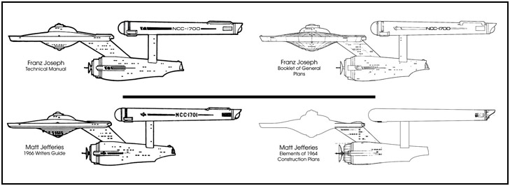
As an example, lest do a comparison between Joseph's reduced information illustrations in his technical manual and his larger drawings in the Booklet of General Plans, and Jefferies' reduced information illustrations seen in TMoST and his larger drawings of the Enterprise model plans.
I would hope that that illustration alone would show the difference in how these illustrations should be studied. After all, how many of you guys pick apart Joseph's technical manual illustrations of the Constitution Class in the same way you've been looking at Jefferies' TMoST illustrations.
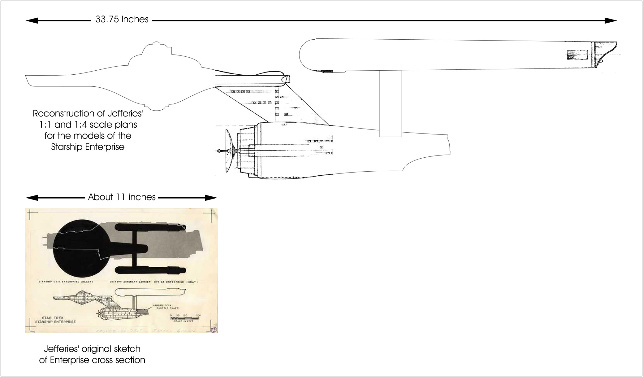
Not to labor on this too much more, but maybe it would be helpful for some to recall the scale at which these drawings were done relative to each other.
And recall that these weren't technical drawings in TMoST, these were reference drawings... designed to give the viewer (that is, the staff of Star Trek) a feel for how things were laid out.
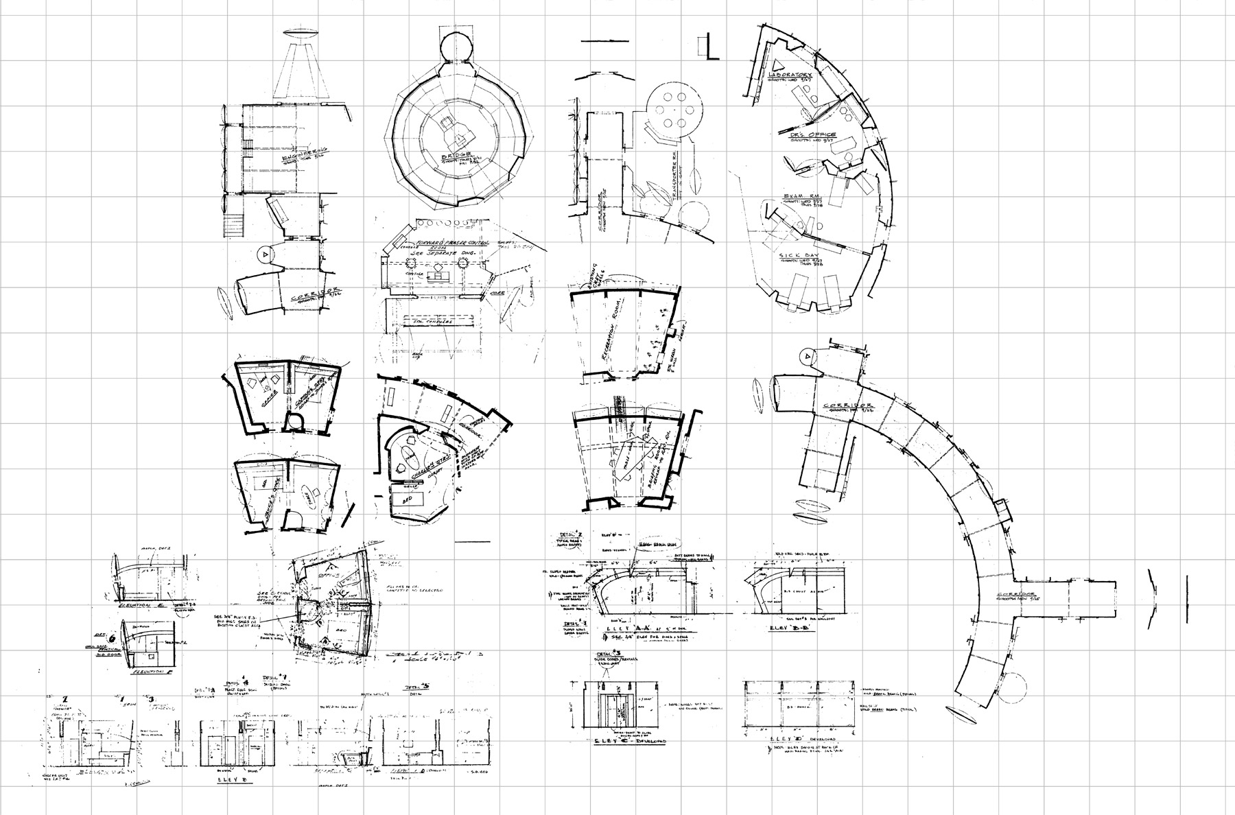
Further, I think many of you guys should attempt to recreate the conditions Jefferies was working under. His curves on the Enterprise didn't match from drawing to drawing because they had to be redrawn each and every time. I have examples of three different primary hull cross section curves from the Phase II Enterprise (all done in 1977), all drawn by Jefferies, and all of the final design... but all hand drawn at vastly different scales to each other.
If you read this stuff as if they were using modern CAD software or illustration software or even 3D software, you're putting yourself on track for some interesting
wild goose chases by over thinking the whole thing.
_____________
With all that having been said, lets look at how one might want to approach the subject of the
undercut. See, looking at Jefferies' plans, I don't think he even thought of there being an
undercut. I think he considered the whole outer ring hanging down as an addition to the structure of the primary hull.
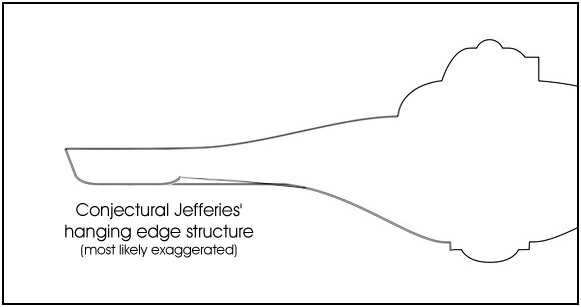
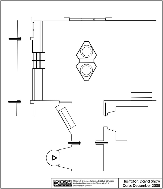
Consider his drawings. All of them (small, medium and large) have a characteristic line along the lower edge of the primary hull. At that line the outer edge changes drastically in direction before reaching it's lowest point. What we see on the models as a somewhat smooth undercut is that hanging structure returning to the plane of that outer line seen on the edge of the primary hull.
Without having more of the plans it is hard to be certain, but this is an estimate of what Jefferies might have been wanting the cross section of the primary hull to look like.
So the next obvious question is... why didn't he get that on the models?
The answer is that he sort of did get it, to a degree, on the 11 foot model. Because the edge on the model changes from being a straight slope to a continuous curve (around to the underside of the primary hull) at about where that point would be.
_____________
While we are on this subject, this brings up an interesting point about the windows on the edge of the primary hull. What I found in my studies of the 11 foot model is that the point at which that curve starts on the outer edge is also the depth of the undercut. More importantly, that area (between the top edge and the beginning of the undercut) is a wood ring structure supporting the model. When the model was modified to be lit, there were rectangular boxes cut into the ring and the windows were lit from them using clear rods placed in holes drilled from the outer edge in.
So the windows are clustered in rows too close together along the center of the edge because that was where the wood was. so the lowest windows/port holes along the edge are above the top of the undercut.
This, of course, won't make any difference on the current version of my plans as all the windows on it were painted on the model at that point. But future versions will take into account the addition of lit windows (and where and how they were placed within the model).
_____________
On a side note... I'll be getting back into the swing of this project as I finish up on my model of the Enterprise. That model has been great for working on details of my plans of the 33 inch model.