-
Welcome! The TrekBBS is the number one place to chat about Star Trek with like-minded fans.
If you are not already a member then please register an account and join in the discussion!
You are using an out of date browser. It may not display this or other websites correctly.
You should upgrade or use an alternative browser.
You should upgrade or use an alternative browser.
Photo request -- Enterprise hangar deck studio miniature
- Thread starter Professor Moriarty
- Start date
But an outstanding accomplishment I must add, thanks for the clarification.
Thank you!
It's been a long time, but I don't recall having anything that hasn't been floating around the internet forever. If I had any higher-res scans given to me I've sure lost them long ago. Hence, my search that led to this thread.What kind of reference materials did you use for the CGI rendering?
So, Petri, any other or better quality photos of this model?
If you mean my rendering, here's a scan I made from my copy of the issue it was in (I lost the original files long ago):

My compliments to Petri Blomqvist on a build that I guessed was either the real deal or the work of Greg Jein.
Thanks, now THAT is a compliment!
By the way, Mr. Blomqvist is the gentleman who provided essential CGI reproductions for the TOS remastering (which obviously required a lot of talent and we saw here how good he is).
Thanks, although the talent is debatable I think! Mostly it required lots of work, dedication and of course collaborating with Gary Kerr.
Thank you Ambassador Petri for clearing up that mystery, and thanks for your inspiring CGI work back in the early 2000's which got me into this maddening hobby.
Sorry about that!
 Love your work by the way, as well as Mark Gagen's, and so many others. I still occasionally do it as well - my latest Enterprise renderings can be found on the Polar Lights 1/350 scale TOS Enterprise model kit and accessory pack boxes (shameless plug)
Wait...if the model walls were in fact "cylindrical" and not conical, there should be no angle on the ceiling beams.
Indeed. But here's a quote from Datin in the Star Trek Communicator article my rendering appeared in:
"According to my figures, (the model) was 10'-2" long, 6'-4" wide by 3'-2" high at the inboard end and 5'-0" wide and 2'-5" high at the outboard end, where the clamshell doors were located."
Based on that, I'd say the model walls were conical, and that's how I built my 3d model as well. By the way, Datin also mentions the scale of the model was one inch to the foot, in other words 1/12.
...Datin also mentions the scale of the model was one inch to the foot, in other words 1/12.
Hmm, just a "hair" too big for the PlayMates Trek action figures from the 90s, but "close enough for gov'ment work".
")
Sincerely,
Bill
Good to hear from you, Petri.
I was obviously misremembering Datin saying the walls were cylindrical. He merely said there were no forced perspective elements in the set as built (i.e.: the galleries didn't diminish in size and elevation like they do on the TMOST drawing).
And thanks for posting the actual size figures. I had been looking over my files and ran across a discussion several of us were having back in November '02 where they came up. I think the main reason I went with a cylindrical profile in my model was to be able to have room for something behind those doors in the side pockets. My goal has been to make it look as much like the original as possible, but still make it functional. It's the same reason I placed windows on the aft side of the control booths when we can see they aren't there in the reverse shots of the miniature. It's also why I lowered two windows on the exterior to align with the observation galleries.
But now I may have to go back and revisit the hangar (and the galleries).
An obsessive fan's work is never done...
M.
That's a beautiful rendering
Now I know who's work I've been admiring ")
FWIW, I was able to get almost everything to line up in the CGI version I'm working on.
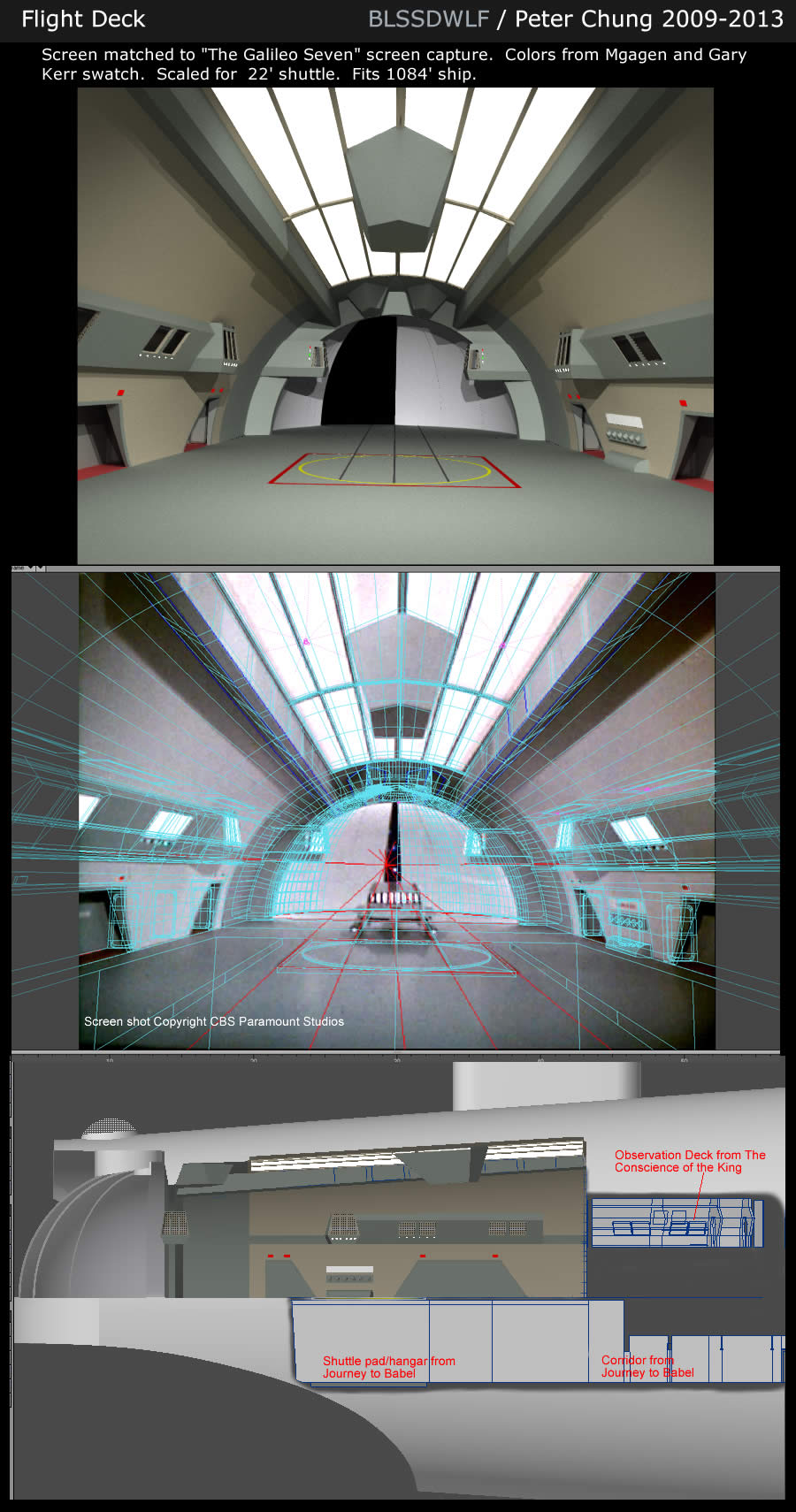
(click for big version)
Here's a quote from Datin in the Star Trek Communicator article my rendering appeared in:
"According to my figures, (the model) was 10'-2" long, 6'-4" wide by 3'-2" high at the inboard end and 5'-0" wide and 2'-5" high at the outboard end, where the clamshell doors were located." ...
Datin also mentions the scale of the model was one inch to the foot, in other words 1/12.
That's just wonderful to have the actual figures of the VFX model.
Now I'm most definitely curious how this would reflect in a properly matched cross-section of the Enterprise assuming a length of 947' compared with the "alternate" length of 1,080'.
Bob
I did some calculations with the Datin figures (based on an overall length of 1,080') and according to these, blssdwlf's cross-section illustrated above is a rather perfect match (great work considering he did not have the Datin figures, as far as I know, and entirely relied on visual data ).
However, it's painfully obvious, that the shuttlebay extends into "pylon space" and apparently more so if we consider an overall length of 947'. On the bright side the lift mechanism of the shuttlecraft elevator no longer needs to be too diagonal.
I'd say that would put the wall with the missing "U"-segment of the observation corridor (i.e. the observation corridor looking aft) in the center of the "pylon space" (I'm aware that for the observation corridor seen in "The Conscience of the King" they redressed the Romulan bridge, but I'm confident that the producers' intention was to present this redressed set and its windows as part of the port side observation corridor seen on the shuttlebay model).
Bob
).However, it's painfully obvious, that the shuttlebay extends into "pylon space" and apparently more so if we consider an overall length of 947'. On the bright side the lift mechanism of the shuttlecraft elevator no longer needs to be too diagonal.
I'd say that would put the wall with the missing "U"-segment of the observation corridor (i.e. the observation corridor looking aft) in the center of the "pylon space" (I'm aware that for the observation corridor seen in "The Conscience of the King" they redressed the Romulan bridge, but I'm confident that the producers' intention was to present this redressed set and its windows as part of the port side observation corridor seen on the shuttlebay model
).Bob
Aside from the doorways (which appear in other episodes as well) I don't see much resemblance between TCOTK observation deck and the BOT Romulan cockpit aside from some angled walls which aren't even at the same angles.
Well, according to blssdwlf's examinations here, the observation corridor set was getting wider the closer it got to the camera (here we do have a case of "forced perspective").
I may have misremembered whether only the doors from the Romulan cockpit were reused or other parts of that set as well.
Bob
I may have misremembered whether only the doors from the Romulan cockpit were reused or other parts of that set as well.
Bob
@Maurice - when I was re-creating the TCOTK obs deck the walls got further apart as they approached the camera. Because the walls were not parallel to each other I had to move the obs deck ahead of the visible flight deck. It still has the exterior wall flush against the outer hull so they have the exterior windows but the interior that looks into the flight deck is angled in.
Angling walls so they're not perpendicular or parallel isn't really forced perspective as such, but it is a common way to design a three-wall set to be more camera friendly.
An earlier version I had "corrected" the angle to make it parallel. When I revisited it, I went for a more accurate approach and left it angled. YMMV on how you would recreate it.
I suspect there is not perfect answer. Each must make his own choice of which details he honors and which he sacrifices.
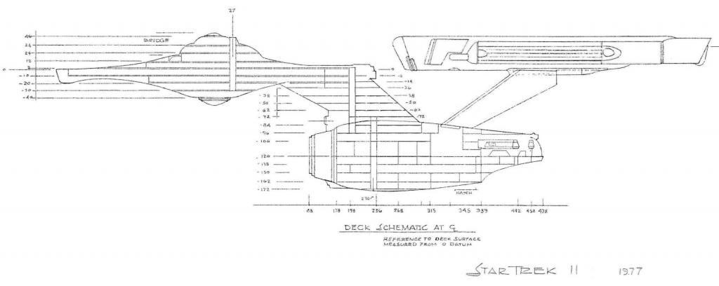
My own approach was to hold on to Jefferies stated 947' length, and his cross section showing the hangar aft of the pylons.
I could never get over the Franz Joseph depiction of the pylons just sticking on to the exterior skin of the hull. I realize that the warp engines' main function is not to generate thrust, but just taking into account the amount of shaking around and even atmospheric friction the ship encounters they must have a pretty robust connection.
I also took to heart Jefferies' location of Engineering on the Phase II cross section. It is still right in front of the hangar (even though the pylon connection points have changed during the refit).
All the above led me to the conclusion that the hangar deck model, whether actually forced perspective or not, was built as it was, primarily, to fit a camera into its end and still have room to pour light in around it. In short I decided not to take too literally what the miniature was, and instead focussed on how the miniature looked.
Admittedly, the hangar that meets all the above requirements does not look exactly like what we saw onscreen. Only a very wide angle virtual lens, placed outside the physical confines of the hangar, can give you similar views. But then, again, the camera that filmed the actual footage was outside that mythical "fourth wall" looking in, too.
Finally, one further point you might consider if you decide to make the hanger as long and conical as the miniature: Where are the windows we see from the outside of the secondary hull if there is only a little wall space between the hangar interior and interior? Unless there is an increasing amount of space between the walls as you go forward, there is apparently no way they can be windows at all.
The amazing thing about all of this, is that the calibre of work that Jefferies and the rest of the production crew of TOS accomplished still inspires and rewards efforts like these forty years later. The quality of work done by fans like Petri, Blssdwlf, Warped9 and many others is nothing short of wonderful.
M.
^^^Yup. Movie and TV sets and models are rarely built to be realistically proportioned. They're built to be practical shooting environments because the only important thing (nitpicky fans aside) is if it looks good on the screen and you can tell your story in it.
I know there are those who disagree with me, but after using the Photoshop perspective tool on the Jefferies cutaway it's more obvious than ever to me that the drawing is in forced perspective (even of the model Datin built might not have been). There are too many "tells" that are readily apparent to anyone whose done serious perspective drawing and worked to accurately scale details towards or away from vanishing points.
I know there are those who disagree with me, but after using the Photoshop perspective tool on the Jefferies cutaway it's more obvious than ever to me that the drawing is in forced perspective (even of the model Datin built might not have been). There are too many "tells" that are readily apparent to anyone whose done serious perspective drawing and worked to accurately scale details towards or away from vanishing points.
^But we now know from the information provided above that the miniature was not built in forced perspective, so maybe that was a test drawing, a rejected proposal for how to build the miniature.
I suspect there is not perfect answer. Each must make his own choice of which details he honors and which he sacrifices.
I'm very much in agreement with this.
I also took to heart Jefferies' location of Engineering on the Phase II cross section. It is still right in front of the hangar (even though the pylon connection points have changed during the refit).
 Sounds like a cross-section I've never seen. All I'm aware of is a rough cross section with a couple of vertical structures where the only discernible thing is the shuttlebay.
How do we know that Jefferies envisioned the engine room to be right in front of the shuttlebay?
Bob
MGagen, is this the one you're referring to?
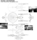
You can see a new hatch is indicated between the new nacelles struts above the newly-expanded room there, and the circular yellow marking on the bottom of the hull seems to be correspondingly moved, too. That's even more apparent on this compliation put together by Shaw:
I think that's why many people (myself included) think the vertical core would have been put there.
You can see a new hatch is indicated between the new nacelles struts above the newly-expanded room there, and the circular yellow marking on the bottom of the hull seems to be correspondingly moved, too. That's even more apparent on this compliation put together by Shaw:

I think that's why many people (myself included) think the vertical core would have been put there.
Similar threads
- Replies
- 10
- Views
- 3K
- Replies
- 482
- Views
- 60K
- Replies
- 6
- Views
- 2K
- Replies
- 1
- Views
- 295
If you are not already a member then please register an account and join in the discussion!