• Welcome! The TrekBBS is the number one place to chat about Star Trek with like-minded fans.
    If you are not already a member then please register an account and join in the discussion!

Modelling and Rendering the TMP Enterprise

i had to compress those images to get them up to photobucket (1mb/pic limit)

here is the link to the HQ originals: http://www.modelermagic.com/?p=15430
there is at least one more top down vies of the hangar deck in the set, as well as many other closeup-highres goodies of other detail parts of the ship :)
 
Hi AnyStar & Wil,

Thanks for the replies. AnyStar, I didn't have that 2nd row of images and I think they will be a big help, especially the view of the deck from above. Until now, I was taking a guess at the shape. That image will nail it.

Wil, I think you are right to some extent. I'm at work at the moment so I can't spend the time looking at this in detail. But at a quick glance, there is a bad deviation to the right of the rightmost vertical gridline. The shape tries to curve to the horizontal when it shouldn't. Straightening that out would make the flow of the mesh into the hangar deck much better. Between that vertical line and the next one in, it's a little less obvious. Maybe at most it deviates in the rightmost third, but barely.

AnyStar, not sure what you meant about the gridline cutting. The only two lines I'd have to cut is that third gridline down and the diagonal gridline on the right. All others would use the lines of the mesh.

Anyway time to get a coffee and get some work done.

Cheers,
S.O.
You're right S.O there is a definite difference with what you have and that top view. It seems to show a continuous taper into aft circle that is the shuttle deck

That should really nail it for you.
 
AnyStar, not sure what you meant about the gridline cutting. The only two lines I'd have to cut is that third gridline down and the diagonal gridline on the right. All others would use the lines of the mesh.

You are asking Anystar, but maybe I can have a shot at explaining it :)
Uploaded a pic,
Cutting the gridlines radial, on the left side, will follow the meshlines and will give a nice render result. But I think you know this already.
What some people do, and I used to do this a long time ago also :sigh:
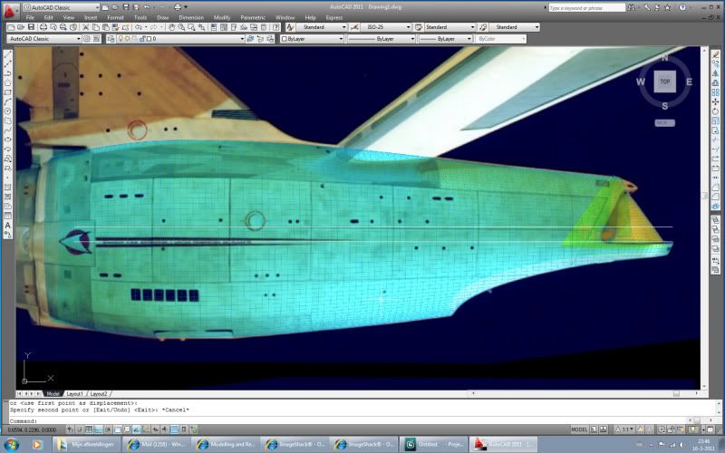
, is to actually model the curve, and cut it horizontally into the hull, like on the right side. Bad thing in this approach, you will never get the gridline follow the meshlines, and second when rendering, the lights will hit it at a different angle as the hull, making it look bad.

As said before, guess you are already doing it this way, maybe someone elase reading this thread can learn from it :)


2.jpg
 
You're right S.O there is a definite difference with what you have and that top view. It seems to show a continuous taper into aft circle that is the shuttle deck

That should really nail it for you.

LOL, havent looked at it, in that way (top view), but you are right about that, that should really nail it :)
 
Thanks guys.

I'm sure I've been to the modelermagic site before, so I can't think why I haven't got all those images. But now I know where they are, I'll be making good use of them.

Just glad I didn't start detailing the sides and then trying to sort out the hangar bay. It would of meant losing a lot of work.

Concerning the gridlines, yes I do a edge bevel followed by a polygon extrude. The new polys would be displaced in the direction of the surface normals (in this case radially). Taking on board what Wil said, I'll lose a chunk off the back and add on a truncated cone. Then onto that I'll add on a sphere along the same lines as I've done with the current iteration. I'm hoping then I'll have the correct shape!:D

Thanks for the feedback, it's much appreciated.

Cheers,
S.O.
 
Just a quick update. Making progress on the back - the hangar deck is now in place.:)

I've changed the slope of the hull following Wil's observation and consequently it looks much better. I'm still cutting out the sides at the moment and got to tidy up the edges of the boolean operations. I've included 2 images - 1 of my hull against the physical model and the other against the Foundation Imaging hull (which I use as a sanity check once in a while as I don't think that model's hull is the correct shape).

Now the questionable part is the 1.3 degree slope I've added to the hangar deck wall. Even with some camera alignment error, I can't explain away the entire slope. So I've added it to see what you think.

Images are very big so I've incuded thumbnails here instead.

Cheers,
S.O.

 
Still trying to figure out where you see a slope, must be some confusion and I am looking not where I am supposed to look :) can you post a close up from an Ent picture, showing it.

Hull looks great now, except for the ortho, which ortho did you use ? is it the FI one?
 
Still trying to figure out where you see a slope, must be some confusion and I am looking not where I am supposed to look :) can you post a close up from an Ent picture, showing it.

Hull looks great now, except for the ortho, which ortho did you use ? is it the FI one?

Hi Wil,

Two images below should demonstrate what I see (at least I hope). I've rotated the first image so that the hangar deck is horizontal. Now I'd expect the centre gridline to have a slight downslope from left to right. So a straight line from each would meet way off the right hand side of the image. Instead it is sloping the other way so the lines meet way off to the left hand side. In the second image the camera is positioned to make the gridline look straight. The hangar deck looks like it is dropping away.

From the side with a little give and take with perspective, it's as if the centre gridline and the line of the hangar deck run parallel. If the centre gridline at the back of the hull is on a slight downslope, it would follow the hangar deck must do the same! The only alternative would be that the centre gridline runs horizontal at the back, which means the the hangar deck would too. But that would contradict that nice straight line in the second image.

So on my camera mapped hull, I've added the slope to the hangar deck so that it matches the background image. If I didn't I'd end up with a deck that's too thick at the back.

That's how I see it anyway. I look at images and something never quite makes sense. I'd welcome some opinions on this as I want to get it right before continuing.


About the ortho - yes it is F.I. I mapped the orthos onto planes to help with positioning. It's a backup because you can't be sure how much camera perspective distorts the shape of the hull.


Some news on the neck. I finally figured out how to use your approach.
  • Take a basic neck, cut off at right-angles.
  • Convert the new edge to a spline.
  • Use Lathe NURBS to sweep the spline around to the vertical.
In my first attempt I used the wrong neck (the tapered one). However it was fairly smooth with a very slight join. Big problem was that the swept shape narrowed too much when it met the saucer. However, I'll try again as I think there's a lot of potential in the approach. Just need to make sure, but one idea might be to take two different shapes - the current edge and a different one for the vertical and merge one into the other via a spline rail arc.
Cheers,
S.O.
 
Ah see, I was looking in the wrong place.

Now your writing about the RHS meeting of the lines ie dropping down of the top gridline is correct, with two remarks:

1. the B&W picture is looking "down" at the top grid line, which is not "fair" to the centerline of the hull, making it look like it is going on a slope, however I measured it and they do converge in that picture ie the distance is less at the back of the ship.
2. the white line in your rotated picture is not the centerline of the hull, the centerline runs in the middle of the banner, yours is way too high in that place, so you rotated the picture wrong, resulting the lines to converge at the LHS. Attached the picture with the correct centerline, and correct rotation, and now you see the centerline and the top gridline converge on the RHS.


Image4-1.jpg


Good luck with the neck, the way you describe it, is the way I did it in AutoCad, only for me hard to explain because AutoCad calls those things different names, like the "new edge, spline" AutoCad will call "edge", and "lathe nurbs" would be called "path" :)
 
Hi Wil,

Still not explaining it properly!

In the B&W image, the centre gridline (the one with the airlock running through it) appears straight due to the camera position. This suggests that if the cylinder is entirely symmetrical and you rotated it so that gridline was at 0, 90, 180 or 270 degrees and viewed it directly from the top, bottom or sides it would be dead straight. In its normal position it lies above the central axis of the cylinder and therefore aft of the airlock it should be on a slight downward slope if you viewed the hull from the side.

Now in both images, the hangar deck seems to match this downward slope or slopes slightly more so.

On the camera mapped hull you edited, the camera is looking down on the hull from 2.4 degrees above the horizontal. So the UFOP decal runs down the side of my mesh. The centre gridline should be on a very slight downward slope being slightly above where the camera's pointing. The hangar deck is slighly below and therefore should be on an upward slope. But instead the slope of the gridline and the LHS of the hangar deck are pretty much the same.

I'll try to edit another image tomorrow night. It's 12:30am - must sleep!

S.O.
 
Just zoomed in extremely on the picture, and saw what you mean, but it is very slightly.
When you take the top view of that bay, the one anystar posted, and make an outline of the bay, rotate it 90 degrees and compare it with the side view, it will never fit to the sideview of the bay, the curve it makes viewed from the top is different from the curve on the side view. So I guess the bay was modeled seperate and then fitted to the back. If so, it wouldn't surprise me if it is on a slope. So my guess is as good as yours, don't know what to advice you here, I would go with a bay NOT on a slope, just because.
 
This may look a little familiar... its what i always go to when i get frustrated from trying to interpret the photos. what you were mentioning about how it was put together is the same conclusion i usually come to also, and the green line is where i sever my hull and begin to shape the hangar section separately.


so far its the only way i can ever come up with curves that seem to match up correctly.

i can see what you are talking about with the slope, but every time i start to try to envision it, i look back at the nacelle struts on your pic, and realize how much above the centerline of the hull the picture is taken from. could it be that the slope you see is simply because we're actually looking "down' to the floor of the hangar instead of straight-on toward it? and the bend of the half circle is mimicing a slope?

or am i completely missing what you fellas are finding:eek:
 
Feel much better now I've slept. It's a tricky one isn't it!

Wil, that was my conclusion. The back was cut off and the hangar bay stuck on. It might simply be that it got stuck on at a slight angle (aka Wonkyprise).

AnyStar, if you look down on the deck the half-circle should result in an upward curve.

I think what I might do, is take the slope and curve it slightly so that it becomes horizontal by the time it reaches the back. I'll play with it tonight and see what I come up with.

Thanks for your patience on this one.

Cheers,
S.O.
 
Just one more thought about this - not the slope issue!

If we are right about the part of the secondary hull being removed, is it possible the hangar deck was formed from a part of that hull?

Take the deck (in the plan) to about the green line, rotate it about the z-axis by 180 degrees and then swing it anti-clockwise around the x-axis by 90 degrees. Would the deck coincide with the hull and be the same shape?

Talking of the plan - that centre gridline has no curve even though it's above the central axis of the cylinder.
 
this has been bugging me all night. that end portion might have been cut off in order to work on the inside of the model and add all the lighting and other parts of the shuttle bay, as well as the rear mounting point.

BUT, i have managed to convince myself you were right about how the shape was made. the end was simply rounded off in an elipse on the lathe, then later cut off to make it into a cap. i've worked up a little study drawing and put it together in a rough animation:

hull1.gif

the purple bits are the limits of where the shaping would have taken place. but as this thing would have been unweildy to say the least when it was cut out in step 2, i assume it was a giant band-saw or jig-saw, the edge that becomes the hangar deck could very easily have ended up with a slope one way or the other!

basically one day i can see it straight the next i can convince myself its crooked! :guffaw::scream: (im going to end up modeling nothing but borg ships from now on, but with no detailing! hahaha)
 
this has been bugging me all night. that end portion might have been cut off in order to work on the inside of the model and add all the lighting and other parts of the shuttle bay, as well as the rear mounting point.

BUT, i have managed to convince myself you were right about how the shape was made. the end was simply rounded off in an elipse on the lathe, then later cut off to make it into a cap. i've worked up a little study drawing and put it together in a rough animation:


the purple bits are the limits of where the shaping would have taken place. but as this thing would have been unweildy to say the least when it was cut out in step 2, i assume it was a giant band-saw or jig-saw, the edge that becomes the hangar deck could very easily have ended up with a slope one way or the other!

basically one day i can see it straight the next i can convince myself its crooked! :guffaw::scream: (im going to end up modeling nothing but borg ships from now on, but with no detailing! hahaha)

I think both of us might be showing the early stages of insanity!:scream:

The ellipsoid idea was a means of shaping the back without disrupting the lines of the mesh. I've dumped that idea for the hangar deck, but might keep it for above the hangar doors and tweak using a FFD.

Must admit that on the train into work, I kept think about that idea in my previous post. Trouble is that I've settled on a revised angle for the slope and started to clean up the edges from the boolean operation. I'm really desparate to make progress now, so may have to accept what I have and push on. I could always lop the back off and try again at a later date.

Cheers,
S.O.
 
You know, the way Franz drew his secondary hull on the constitution was also very fluid and teardrop like. I wonder if that had an influence here.
 
You know, the way Franz drew his secondary hull on the constitution was also very fluid and teardrop like. I wonder if that had an influence here.

Not quite. FJ drew a lot of his artwork based on material from "The Making of Star Trek", which used one of the miniatures for the hull guide, which also had that rounded 'teardrop' shape.
 
There were even two of those teardrop hulls. One for his Constitution/Ent blueprint set, and one even longer version used in his Tech Manual. I have seen some folks place a less blocky saucer hull on that fluid shape--I think McMaster had a nice combination of FJ and waht we saw on screen. Each artist leaves his own signature--and that's a good thing.
 
Hi Folks,

Vance & publiusr - I think the hull is a teardrop shape, assuming that my camera is mapping the hull correctly onto the background images.

I had to go back to an earlier step last weekend due to the bottom gridline. I cut a plane into the mesh and the results of the boolean operation were bad. Even if I had cleaned it up, it would have left a number of issues.

So instead of cutting and tidying, I cut and then redistributed a large number of points over the surface of the hull between the centre gridline and the area outlined by the model stand. Then over the week (time permitting), I remodelled the hangar deck and recut the arc.

The slope on the hangar deck makes more sense now I've redistributed the points. The "horizontal" edges of the hull mesh now flow into the hangar deck.


It's much tidier and yet it leaves me with so much to do. I'm now looking at the top gridline and all vertical gridlines aft of the airlock.
  • The top gridline tends to move slightly higher as it approaches the top of the hangar bay. It's important because the height of the panels above the centre gridline look wrong compared to panels below the gridline. I don't want to do this! Some of the problem can be removed by rotating the centre gridline points down by a third of a polygon.
  • I think the vertical gridlines are not quite vertical! I'm wondering if the lean I see on some of the lines is because the model builders used the centre gridline as the horizontal and drew at 90 degrees to that. As the gridline slopes down aft of the airlock, the top of the vertical lines lean to the right.
Or of course I'm completely wrong and most of this can be attributed to optical distortion in the physical camera lens!

Cheers,
S.O.


If you are not already a member then please register an account and join in the discussion!

Sign up / Register


Back
Top