-
Welcome! The TrekBBS is the number one place to chat about Star Trek with like-minded fans.
If you are not already a member then please register an account and join in the discussion!
You are using an out of date browser. It may not display this or other websites correctly.
You should upgrade or use an alternative browser.
You should upgrade or use an alternative browser.
Modelling and Rendering the TMP Enterprise
- Thread starter Science Officer
- Start date
looking great so far, and you're absolutely right, the area at the back is a pain to get everything cut into the right shapes and smoothed correctly :{ i'm not looking forward to starting mine next week at all. haha
I usually cut my cylinder off completely, at an angle on the line of the last deflector-grid channel back there, and then just shape the entire area by hand. It seems easier to me than trying to morph the cylinder into the shape by just cutting out the deck and rear wall where the doors are.
idk if you are still worying about the neck, but as i was going over ref pics of it today myself, thought i'd share a couple shots that help define the curve, based on that stripe:


hope it helps! i'll be posting pics of my new model later tonite too!
Last edited:
looking great so far, and you're absolutely right, the area at the back is a pain to get everything cut into the right shapes and smoothed correctly :{ i'm not looking forward to starting mine next week at all. haha
I usually cut my cylinder off completely, at an angle on the line of the last deflector-grid channel back there, and then just shape the entire area by hand. It seems easier to me than trying to morph the cylinder into the shape by just cutting out the deck and rear wall where the doors are.
idk if you are still worying about the neck, but as i was going over ref pics of it today myself, thought i'd share a couple shots that help define the curve, based on that stripe:
hope it helps! i'll be posting pics of my new model later tonite too!
Hi AnyStar,
Think I've got all those pictures - but thanks for posting anyway!
I think I can see how to improve the neck. It would mean going way back to fix things, but it would primarily help with the nose which irritates me on occasion.
I haven't had much spare time to work on the secondary hull this week. But good progress has been made in understanding the shape and how it relates to the reference images. I set up a proper background image and adjusted a camera to give the best alignment possible. I've tweaked out most of the errors. I've yet to do the rear. The shape is good - the only deviation is the bottom (3rd down) deflector grid line, which doesn't flow with the hull. It must be a straighter line. Shouldn't be difficult to cut this into the polygons.
Cheers,
S.O.

Just a quick note. I've been looking at the bottom deflector gridline tonight to work out what needed to be done to add it to the secondary hull.
It appears that starting from the right-most arboretum window, the line runs dead straight across almost horizontally. I've currently got it on a slight upward slope of only 0.5 degrees. That aside the hull appears cylindrical and with the exception of some of the windows, all other features follow the lines of the mesh.
S.O.
Lovely work being done here... Keep it up!
I was wondering about the original TMP Enterprise shooting model. Whether it still exists or not. But wouldn't it be fantastic if the original TMP paint job was reinstated. Either by the guy who originally did it or someone who is insane enough to tackle it...!
I'd really, really like to see that.

I was wondering about the original TMP Enterprise shooting model. Whether it still exists or not. But wouldn't it be fantastic if the original TMP paint job was reinstated. Either by the guy who originally did it or someone who is insane enough to tackle it...!
I'd really, really like to see that.
Lovely work being done here... Keep it up!
I was wondering about the original TMP Enterprise shooting model. Whether it still exists or not. But wouldn't it be fantastic if the original TMP paint job was reinstated. Either by the guy who originally did it or someone who is insane enough to tackle it...!
I'd really, really like to see that.
yes, its still out there :}~ and as for the paintjob, somewhere buried in my favorites folder is a link to a webpage of just that, a sort of diary of his proccess and even a timeline of painting it. full of pics too, although as you can imagine they're old and low-res
 i'll see if i cant find the link.
edit: found it!
http://www.olsenart.com/strek.html
Lovely work being done here... Keep it up!
I was wondering about the original TMP Enterprise shooting model. Whether it still exists or not. But wouldn't it be fantastic if the original TMP paint job was reinstated. Either by the guy who originally did it or someone who is insane enough to tackle it...!
I'd really, really like to see that.
Thanks,
I believe it was sold at a Christies auction a while back. Current whereabouts unknown.
I very much doubt that the model can be restored to its former glory. ILM did some repainting on it following its change to being the NCC-1701-A. They also coated it with something to tone down the pearl effect - I think (not sure) because it interfered with the blue screen.
So some parts of the model may have lost the original paintjob, others may be buried under the ILM paintjob and whatever's left will be coated to tone down the pearl effect.
Agree it would be nice to see if it could be restored - but the effort might be on the scale of restoring antique paintings. It's still a shame that with the exception of the TMP film itself we have no decent colour references of the original model.
Of course many a hobbyist has had a go. If you haven't seen some decent attempts, I recommend the HobbyTalk site. I do remember one guy who was achieving some good results, but can't remember the exact thread. Might be best to google against the site on the images page.
Cheers,
S.O.
I do remember one guy who was achieving some good results, but can't remember the exact thread.
http://www.hobbytalk.com/bbs1/showthread.php?t=273113&page=18&highlight=tmp
Go down to post 261, and have a look at the movies posted.
AnyStar and wjaspers...
Great links guys, I had visited the olsenart site some years ago but had since lost the link. A great insight into building the new "Old Girl" Amazing paint work. Probably one of the best models ever made, regardless of genre. I miss that about modern films where CGI is almost always the norm now.
As for the hobbytalk link, that was an eye opener, trekmodeler is a phenomenon! How great is it that he is making money doing something that was originally just a hobby for him? Bit like me in a way. Except my hobby was fiddling with computers.
Just wanted to thank for the links. Don't mean to de-rail the thread!")
Great links guys, I had visited the olsenart site some years ago but had since lost the link. A great insight into building the new "Old Girl" Amazing paint work. Probably one of the best models ever made, regardless of genre. I miss that about modern films where CGI is almost always the norm now.
As for the hobbytalk link, that was an eye opener, trekmodeler is a phenomenon! How great is it that he is making money doing something that was originally just a hobby for him? Bit like me in a way. Except my hobby was fiddling with computers.
Just wanted to thank for the links. Don't mean to de-rail the thread!
Hi Folks,
After a weekend of "trying stuff out", I think I'm starting to move forward on the hangar bay.
As AnyStar mentioned, this is a tricky one, but I didn't want to resort to shaping by hand. My approach (which is a bit different to AnyStar) is to cut the back of the hull off vertically and bolt on half a sphere. The cutoff occurs at the position of the rear navigation light. The trouble with that is you get a non-smooth suface at the join. On the cylinder the lines are converging and on the sphere the lines are horizontal. This messes up the illumination on the hull.
I couldn't figure out a solution until yesterday. I added a Freeform Deformer to the sphere and made the sphere slightly ellipsoid. I deformed it sufficiently so that lines of the sphere now converge like the lines on the cylinder. Illumination problem solved.
Other tasks included:
S.O.


After a weekend of "trying stuff out", I think I'm starting to move forward on the hangar bay.
As AnyStar mentioned, this is a tricky one, but I didn't want to resort to shaping by hand. My approach (which is a bit different to AnyStar) is to cut the back of the hull off vertically and bolt on half a sphere. The cutoff occurs at the position of the rear navigation light. The trouble with that is you get a non-smooth suface at the join. On the cylinder the lines are converging and on the sphere the lines are horizontal. This messes up the illumination on the hull.
I couldn't figure out a solution until yesterday. I added a Freeform Deformer to the sphere and made the sphere slightly ellipsoid. I deformed it sufficiently so that lines of the sphere now converge like the lines on the cylinder. Illumination problem solved.
Other tasks included:
- Cutting out the large curve and tidying up the resulting points and polys.
- Adding a FFD to get that slope on the hangar deck.
- Adding another FFD to widen the deck (in the x-axis). It was of course slightly eillipsoid. I've pulled it wider than a circle because reference images don't suggest a perfectly circular deck. However this may need further tweaking once I get the doors in.
S.O.
Hi Folks,
Well I've started cutting out the hangar deck. Looking promising but one thing is bugging me and I could do with a second opinion!
The hangar deck -is it horizontal or on a slight downward slope? To me it looks like a slope and it kind of levels out inbetween the ENTERPRISE decal. I've tried to convince myself it's just the camera, but I see it in three images at different angles. Other models have it horizontal. Also my deck is a bit too thick and it would thin out nicely if I added this slope.
Another concern is the cutout under the hangar deck. From the back, the cutout outline curves into the doors whilst on other models it generally tries to curve into the edge of the hangar bay (forming a large oval). Has anyone got a reference image of the rear?
Cheers,
S.O.
The hangar deck -is it horizontal or on a slight downward slope? To me it looks like a slope and it kind of levels out inbetween the ENTERPRISE decal. I've tried to convince myself it's just the camera, but I see it in three images at different angles. Other models have it horizontal. Also my deck is a bit too thick and it would thin out nicely if I added this slope.
Looks pretty straight to me.
Another concern is the cutout under the hangar deck. From the back, the cutout outline curves into the doors whilst on other models it generally tries to curve into the edge of the hangar bay (forming a large oval). Has anyone got a reference image of the rear?
It needs to run into the doors, yours is correct. The oval happens when you do not have the right curve of the cut out, or when your model is too heavy at the back.
Hi Wil,
Thanks for the reply, although it wasn't the one I was hoping for!

At the moment I think the hangar deck is about one polygon too thick. Half of that I think can be lost via the cutout under the hangar bay. But that still leaves half a polygon, which if it can't be lost from the bottom, must be lost from the top.
I was hoping working on the idea that the side walls of the deck would slope down very slightly (no more than 1 degree), then level out over the ENTERPRISE decal.
I'll have to recheck my camera aligned reference.
Thanks,
S.O.
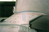
Checked on that for you, think it is one polie on the bottom, something like the attached picture, please check this with your ref:
And about that oval curve you mentioned, running into walls instead of into the doors, take a look at this picture, not a perfect back view, but I think it can help : http://movies.trekcore.com/gallery/albums/tuc_other/posters/tuc_advance_spain.jpg
And about that oval curve you mentioned, running into walls instead of into the doors, take a look at this picture, not a perfect back view, but I think it can help : http://movies.trekcore.com/gallery/albums/tuc_other/posters/tuc_advance_spain.jpg
i've always worked under the assumption that the hangar deck was straight also, but as for your sphere back there... i never thought it through enough to realize that that bump on top and the slope beneath the hangar floor would both be taken care of in a single sphere edge! i'll have to try out your method when i get to that part of mine
Wil - thanks for digging up that poster. It's probably as close a reference as we've got, although being a painting, there maybe some artistic interpretation going on there. I also looked at a screenshot of the Enterprise approaching the Genesis planet in TSFS. Again some minor hints it might be right but nothing concrete.
AnyStar - can we take it that you're working on the neck at the moment?
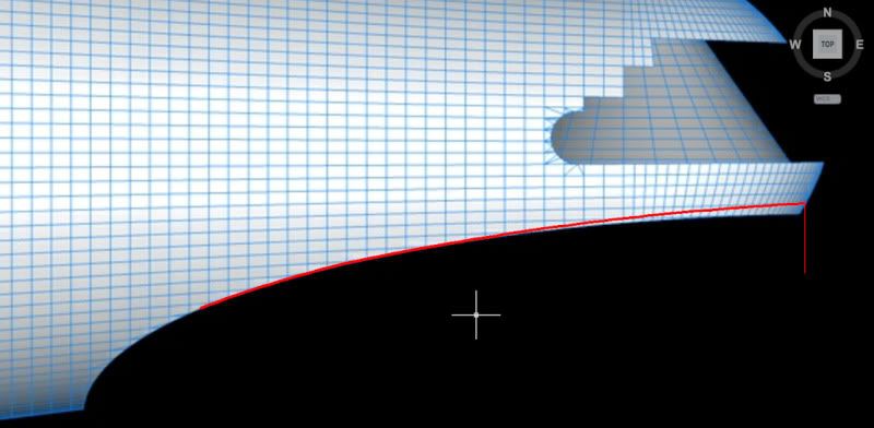
Anyway back to the sloping deck problem. I've attached a thumbnail to my camera mapped hull. As you'll see it suggests the hull is cylindrical. Gridlines match up well with the exception of that lower 3rd line, which I think is nearly horizontal. The alignment between camera and hull isn't bang on, so there maybe some slight deviations that can be attributed to that.
It's the first time I've rendered this view so large. It already shows some deviation. Wil, you are right, the cutout needs a slight change. I'll sort that out this weekend.
Now to the deck - my circular cutout is slightly misplaced in the horizontal, so that will need to be redone too. The deck wall drops away by about half to one polygon by the time we reach the back. Some of that will be down to the curvature of the deck (in the xz plane). But there seems a little too much to be accounted for by that and the camera.
Cheers,
S.O.

AnyStar - can we take it that you're working on the neck at the moment?
Anyway back to the sloping deck problem. I've attached a thumbnail to my camera mapped hull. As you'll see it suggests the hull is cylindrical. Gridlines match up well with the exception of that lower 3rd line, which I think is nearly horizontal. The alignment between camera and hull isn't bang on, so there maybe some slight deviations that can be attributed to that.
It's the first time I've rendered this view so large. It already shows some deviation. Wil, you are right, the cutout needs a slight change. I'll sort that out this weekend.
Now to the deck - my circular cutout is slightly misplaced in the horizontal, so that will need to be redone too. The deck wall drops away by about half to one polygon by the time we reach the back. Some of that will be down to the curvature of the deck (in the xz plane). But there seems a little too much to be accounted for by that and the camera.
Cheers,
S.O.

i still have not gotten that far yet i threw out my sensor array and have been re-working it today...
as for the gridlines, the last time i modeled that hull, instead of cutting lines in horizontally, it looked better if i just used the radial edges of the surface itself. and on your image there, i'd say that given camera distortion, your edges could be used the same way. i'm guessing those lines were scribed while that thing was still attached to the lathe anyway, using the bench as a guide and just spinning the thing around to each scribe location.
i was studying images of that hangar deck portion today since reading your earlier post, here's a couple of the best closeups i have and some of the best head on shots ive come across, maybe they'll help you out some (if you dont already have these too!)


i threw out my sensor array and have been re-working it today...as for the gridlines, the last time i modeled that hull, instead of cutting lines in horizontally, it looked better if i just used the radial edges of the surface itself. and on your image there, i'd say that given camera distortion, your edges could be used the same way. i'm guessing those lines were scribed while that thing was still attached to the lathe anyway, using the bench as a guide and just spinning the thing around to each scribe location.
i was studying images of that hangar deck portion today since reading your earlier post, here's a couple of the best closeups i have and some of the best head on shots ive come across, maybe they'll help you out some (if you dont already have these too!)


as for the gridlines, the last time i modeled that hull, instead of cutting lines in horizontally, it looked better if i just used the radial edges of the surface itself.
Ah yes, radial, not horizontally, it is going to look strange when rendered.
Nice pictures !
I've attached a thumbnail to my camera mapped hull. As you'll see it suggests the hull is cylindrical. Gridlines match up well with the exception of that lower 3rd line, which I think is nearly horizontal. The alignment between camera and hull isn't bang on, so there maybe some slight deviations that can be attributed to that.
Looking at your picture and the gridlines. Ofcourse there is camera distortion, but if you rendered your mesh with a camera the distortion should be the same for the mesh, anyhow, my observation:
the top gridline runs a bit higher at the end than the meshline, the bottom gridline runs lower at the end than the meshline.
Reason: your hull is too narrow to the end.
Checked you picture, but it seems (and you are not the only one doing this) you have a curve (inwards) from the nacelle struts towards the end of the hull, but it needs (my $0,02) to be a straight line.
Hi AnyStar & Wil,
Thanks for the replies. AnyStar, I didn't have that 2nd row of images and I think they will be a big help, especially the view of the deck from above. Until now, I was taking a guess at the shape. That image will nail it.
Wil, I think you are right to some extent. I'm at work at the moment so I can't spend the time looking at this in detail. But at a quick glance, there is a bad deviation to the right of the rightmost vertical gridline. The shape tries to curve to the horizontal when it shouldn't. Straightening that out would make the flow of the mesh into the hangar deck much better. Between that vertical line and the next one in, it's a little less obvious. Maybe at most it deviates in the rightmost third, but barely.
AnyStar, not sure what you meant about the gridline cutting. The only two lines I'd have to cut is that third gridline down and the diagonal gridline on the right. All others would use the lines of the mesh.
Anyway time to get a coffee and get some work done.
Cheers,
S.O.
Similar threads
If you are not already a member then please register an account and join in the discussion!