• Welcome! The TrekBBS is the number one place to chat about Star Trek with like-minded fans.
    If you are not already a member then please register an account and join in the discussion!

My TOS shuttlecraft (continued)...

Re: My TOS shuttelcraft (continued)...

The annotations will be regarding capabilities and construction.

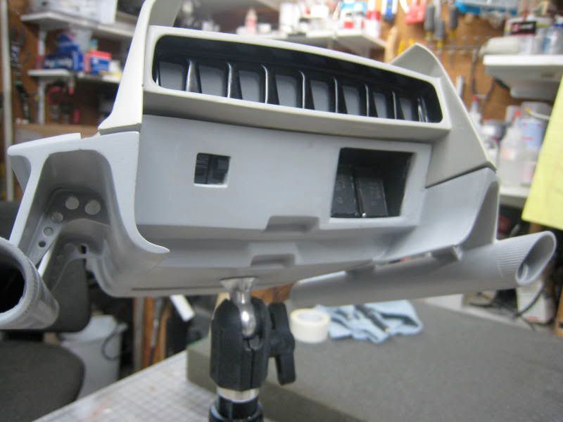
My general idea is that the inner hull is composed of thin multiple layers. The innermost layer is the one we see inside, preformed molds of advanced polycarbonate or plastisteel (sounds more TOS). The next layer outward is thermal insulation. Then comes a semi fluid hull sealant that flows into a breach upon reacting to sudden changes in atmospheric pressure and then solidifies as a temporary plug. Finally is another layer of plastisteel. The spaceframe and outer hull are made of duranium alloys, of course.


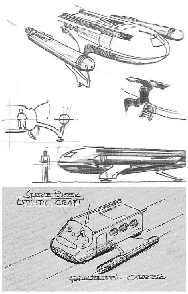
Coming accross this image in the Randy Cooper's shuttlecraft thread on the Hobbytalk boards has given me cause to consider tinkering with the detailing on the underside of my shuttlecraft drawings. It could give me a smidgen more room under the floor for mechanical bits.
rear.jpg
 
Last edited:
Re: My TOS shuttelcraft (continued)...

Try this.

ShuttleScale-1.jpg


And this is my last take on how this project will pan out. Emboldened items are completed.

Class F and H Shuttlecraft Plans:
Sheet 0 Starfleet Shuttlecraft Cover Page
Sheet 1 Class F Shuttlecraft Port Elevation
Sheet 2 Class F Shuttlecraft Starboard Elevation
Sheet 3 Class F Shuttlecraft Bow Elevation
Sheet 4 Class F Shuttlecraft Aft Elevation
Sheet 5 Class F Shuttlecraft Top Plan
Sheet 6 Class F Shuttlecraft Bottom Plan
Sheet 7 – Class F Shuttlecraft Port Cutaway
Sheet 8 – Class F Shuttlecraft Starboard Cutaway
Sheet 9 – Class F Shuttlecraft Bow Cutawaay
Sheet 10 – Class F Shuttlecraft Aft Cutaway
Sheet 11 – Class F Shuttlecraft Deck Plan
Sheet 12 – Class F Shuttlecraft Ceiling Plan
Sheet 13 – Class F Shuttlecraft History & Specifications
Sheet 14 – Class F Shuttlecraft Artist’s Showcase
Sheet 15 – Class H Shuttlecraft Port Elevation
Sheet 16 – Class H Shuttlecraft Starboard Elevation
Sheet 17 – Class H Shuttlecraft Bow Elevation
Sheet 18 – Class H Shuttlecraft Aft Elevation
Sheet 19 – Class H Shuttlecraft Top Plan
Sheet 20 – Class H Shuttlecraft Bottom Plan
Sheet 21 – Class H Shuttlecraft Port Cutaway
Sheet 22 – Class H Shuttlecraft Starboard Cutaway
Sheet 23 – Class H Shuttlecraft Bow Cutawaay
Sheet 24 – Class H Shuttlecraft Aft Cutaway
Sheet 25 – Class H Shuttlecraft Deck Plan
Sheet 26 – Class H Shuttlecraft Ceiling Plan
Sheet 27 – Class H Shuttlecraft History & Specifications
Sheet 28 – Class H Shuttlecraft Artist’s Showcase
Sheet 29 – U.S.S. Enterprise Shuttlecraft Complement
Sheet 30 – Starflight Regimes
Sheet 31 – Starfleet Shuttlecraft Project Notes

Supplemental Sheet 1 – Class F/H Shuttlecraft Inner Hull Primary Views #1
Supplemental Sheet 2 – Class F/H Shuttlecraft Inner Hull Primary Views #2
Supplemental Sheet 3 – Class F/H Shuttlecraft Spaceframe Primary Views #1
Supplemental Sheet 4 – Class F/H Shuttlecraft Spaceframe Primary Views. #2
Supplemental Sheet 5 – Shuttlecraft Galileo Photo Enhanced Image*
Supplemental Sheet 6 – Shuttlecraft Copernicus Photo Enhanced Image*


Forthcoming Projects:
-TAS shuttlecraft: “real” world versions of the TAS scoutship, heavy lander and aquashuttle designs.
- Pre TOS shuttlecraft: adapted versions of Matt Jefferies’ initial and early Galileo shuttlecraft concepts.
- TMP era shuttlecraft: two movie era shuttlecraft as well as a conceptual TMP era Class F design.
- “The Cage” era U.S.S. Enterprise.
 
Re: My TOS shuttelcraft (continued)...

Wow, seeing the shuttle next to the VW and on the Enterprise really gives me a personal sense of realism for it. And it seems like you're actually further along with this than I thought, or is there a lot of the time consuming work still ahead?
 
Re: My TOS shuttelcraft (continued)...

^^ I actually have quite a bit of the cutaway views for the Class F done, but they are undergoing revisions because I've decided to detail the inner hull and spaceframe to be accurate in my cross sections.

I'm also making small corrections to my finished drawings even though technically they're complete. My reasoning is for a bit more authenticity and because these plans are not strictly in the pure blueprint style but executed with a measure of artistic style.

And, yes, it can be quite time consuming. But I must enjoy it for it to hold my interest and motivate me to continue. :)
 
Re: My TOS shuttelcraft (continued)...

I've been following RedSpar's progress regarding his take on MJ' early concept for the TOS shuttlecraft. It's fascinating even though I might disagree with some of his interpretations.

But it's gotten me to thinking down the road when I've gotten the Class F and H and then the TAS ships done and out of the way.

I've extrapolated from some of MJ's early concepts and even basic sketches before and my approach is not to take them too literally. By that I mean is that an early concept is not a finished design. As you flesh it out you find better solutions to ideas and as it evolves a more realized form takes shape.

To that end down the road I'll be tackling two of MJ's early ideas on the shuttlecraft. I'll adapt his intial concepts without allowing myself to be constrained by early solutions and evolve the designs into something that should hopefully look at home in the TOS universe, or more particularly the pre TOS era.

EarlyMJ.jpg


But back to present day matters. I've been pondering the antideluvian looking support braces that the fullsize mockup has under the stabilizers. They were needed, no doubt, to help support and strengthen the structure of the mockup. Of course I rejected them based on the thought that they looked wholly out of place and created even more aerodynamic drag on a vehicle design with little in the way of aerodynamics to begin with. But within the TOS universe I also reasoned that if they can build a massive starship with huge engines affixed to the hull by seemingly too slender support pylons without any propblem whatsoever in terms of structural stress, than something like the shuttlecraft's thin stabilizer and pylons should be a snap.

That said I'm pondering an idea of beefing up the structure under the stabilizers anyway. I've an idea on how it could be done in such a way that it wouldn't be visible or apparent unless you looked right under the stablizers, much as the mockup's braces weren't very apparent except from certain angles from the front or rear. And my idea would be even less apparent.

Any thoughts?
 
Last edited:
Re: My TOS shuttelcraft (continued)...

As always, I'm a tad overwhelmed by your post, good sir. However, I think that beefing up the stabilizers is a good thought and as you say, you have the leeway.
 
Re: My TOS shuttelcraft (continued)...

I thought the design you came up with for the art contest looked kinda like what Jeffries "space dock Utility craft/ personal carrier" might have 'evolved' into if he'd developed it further?
 
Re: My TOS shuttelcraft (continued)...

I thought the design you came up with for the art contest looked kinda like what Jeffries "space dock Utility craft/ personal carrier" might have 'evolved' into if he'd developed it further?
What art contest? I don't recall submitting anything for a contest.
 
Re: My TOS shuttelcraft (continued)...

Sorry, I momentarily got you confused with Ptrope, :alienblush: consider it a compliment. It was late when I posted and I guess I was half asleep? :lol:
 
Re: My TOS shuttelcraft (continued)...

You know for about two years I've been rendering my drawings with Illustrator CS and Photoshop CS (I'd love CS4, but I can't afford it) and yet I've never exploited a portion of what these programs are capable of.

Last night while I was working I did a little casual exploring and came across some other tools and capabilities that I had never realized were so readily at hand and can make my life so much easier. I swung back and forth between excitement over being able to do certain things more effectively and thinking myself so stupid for not having found and used those tools for so long.

After a tiring, frustrating, bummer day yesterday it was nice to experience something positive.

One of the things it might help me with is in terms of scale. I might be able to stretch inches here and there to gain some added interior space without increasing the size of the exterior. I'm mostly concerned with cabin length and height rather than width. Every little bit helps.

And I'm pretty sure that I can add some extra substance under the stabilizers that will be unobtrusive and not look like an add-on.
 
Re: My TOS shuttelcraft (continued)...

So, what were the tools you discovered? I'm sure some of us wouldn't mind hearing the occasional tip like that.
 
Re: My TOS shuttelcraft (continued)...

Illustrator alows you to know the dimensions of your lines (paths) and/or objects. But I stupidly didn't realize how to conveniently and easily changes on objects size or scale by simply entering in the value I wanted rather than just scaling the object or line manually. I knew that tool had to be there somewhere, but I hadn't realized where it was exactly so that I could turn it on and have it at hand whenever I wanted it. Scaling manually is cumbersome and time consuming. Now I can draw in scale because I can do the math in my head (or on a calculator) and then just enter the size I want.

Illustrator also has a host of effects I hadn't realized were there before. You can even draw 3D shapes and effects even though it isn't 3D modeling, which is a shame because I think Adobe might be an easier program to understand for 3D modeling (if they had one) than all the others I've seen. I can also envision an Adobe CAD program that would be rather more accessible than the others I've seen.

You can also custom build your own library of colour swatches as well as brushes and symbols and other things as opposed to relying solely on what seems to be immediately available. This is a great help in achieving consistent colours.
 
Re: My TOS shuttelcraft (continued)...

The numeric scaling is something I almost always overlook too. We learned a bit about doing 3D shapes in Illustrator in school too, but didn't spend much time on it because (paraphrasing my teacher) 'if you ever really want to create something in 3D, you'll probably model it in CAD or Maya.'

Yeah, I need to learn more about that. It's remarkable how little of the massive components of those programs any one person probably actually uses.
 
Re: My TOS shuttelcraft (continued)...

I also like that the lines are scalable proportionately. It means I can draw something large with lines of varying thickness and when I reduce it to fit the page layout everything will remain exactly the same appearance wise rather than lines beginning to bunch up and overlap because they've retained their original thickness while the blank spaces in the object have decreased in size. And drawing large allows me to have more precision and seeing things more clearly in terms of thinking in fullsize terms.

Using lines of varying thickness also allows me to add a small sense of 3D to my drawings. Because the thickness of the line can suggest different things to the eye.

Also I'm toying with another idea. Presently I'm using a line .1 points in thickness to denote the centerline of a radial curve or surface similar to what Phil Broad did on his construction drawings. However, my drawings are not strictly in the blueprint style as they're not construction drawings and I don't have dimensions and dotted lines denoting hidden features all over the page. There's meant to be a rather more artistic style to the drawings. As such instead of using a very thin line to mark the centerline of a curved surface I'll try a thin blurred line. This accomplishes what I want and better suggests a sharp change in curvature.

What this project has made really apparent to me is that all three versions of the shuttlecraft on TOS were production compromises and quite distinct from each other. I can understand the fullsize mockup being constructed the way it was, but why didn't the miniature "flying" model more closely resemble the 22ft. mockup?
 
Last edited:
Re: My TOS shuttelcraft (continued)...

One of the biggest discrepencies between the flying miniature and the full size mockup is the underside detail. I wracked my brain trying to understand how they could get the small model's underside the way it is while it looks so different on the fullsize mockup. It's quite likely they just flattened out the shape of the small model's underside without considering the implications in regards to how it compared to the fullsize mockup.

I could replicate the small model, but it would mean distorting the shapes of the bottom and aft and possibly bow as well, and then it would mean losing under-the-deck space inside the craft. And so I'll just tick with what I have presently.

That said, though, I am going back and correcting some things I feel I could do better on the sheets I've already completed.

Now, I've a question for Phil Broad and all you other learned treknologists out there: were the braces under the stabilizers put there just to strengthen the fullsize mockup's structural support or were they intended as part of the vehicle's design all along? I ask because the small flying miniature wouldn't have needed such braces and yet it does have them anyway.
 
Re: My TOS shuttelcraft (continued)...

Those braces are very strange -- I feel rather sure they are part of the design. They have a distinctly retro-future, space-brace look to them, like something one would see on Seaview or the Jupiter II. And yet they are so un-aerodynamic that they render the stub "wings" useless for any stabilization, and would actually interfere with flight. If there is any way to interpret them as bracing and eliminate them from the design, I would.

The only rationalization I can think of is envisioning the shuttlecraft flying more like a helicopter (with antigrav instead of rotors) rather than as an airplane. I simply cannot envision the shuttlecraft flying with any measure of aircraft like grace otherwise.

I'm envisioning a way to beef up the area under the stabilzers and support pylons while being much less obvious than the braces we see onscreen. OTH if I learn that they were indeed intended as part of the design then I can include them as such.
 
Last edited:
Re: My TOS shuttelcraft (continued)...

I would tend to agree with the helicopter comparison too. If that's the case, then there's no point in needlessly worrying about and removing the braces.

Then again, could the material the struts themselves are made of be strong enough without the braces, regardless of why they were 'really' there?
 
Re: My TOS shuttelcraft (continued)...

Those braces are very strange -- I feel rather sure they are part of the design. They have a distinctly retro-future, space-brace look to them, like something one would see on Seaview or the Jupiter II. And yet they are so un-aerodynamic that they render the stub "wings" useless for any stabilization, and would actually interfere with flight. If there is any way to interpret them as bracing and eliminate them from the design, I would.

The only rationalization I can think of is envisioning the shuttlecraft flying more like a helicopter (with antigrav instead of rotors) rather than as an airplane. I simply cannot envision the shuttlecraft flying with any measure of aircraft like grace otherwise.

I'm envisioning a way to beef up the area under the stabilzers and support pylons while being much less obvious than the braces we see onscreen. OTH if I learn that they were indeed intended as part of the design then I can include them as such.
Well, the shuttlecraft IS utterly and completely non-aerodynamic. It's a brick, nothing more, from that standpoint.

I have no problem with the braces, because they can't harm the design. The design simply doesn't work as an aerodynamic concept in any fashion.

Now, the thing to think about is "how does this thing fly?" Obviously, it doesn't rely on aerodynamic lift. So it has to have antigravitational capability. That makes it SOMEWHAT like a helicopter... in that "lift" is unrelated to "velocity."

On the other hand, helicopters are capable of pretty limited in-atmosphere velocities. Fly them too fast (in ANY direction, not just forwards) and they'll rip themselves apart. The same would be the cases with this ship.

So... key to figuring out this design is figuring out its flight profile, in-atmosphere.

I'd say that the ship isn't designed to fly fast in an atmosphere at all. It's intended to drop, almost vertically, from vacuum to the surface. But even then, for the distances we're talking about, you need to have something that makes it "semi-aerodynamic," don't you?

SO... the shuttlecraft needs something akin to a deflector shield system operating full-time when flying in an atmosphere, creating a "second skin" (potentially being reshaped in real-time for aerodynamic control?) You simply can't get away from that, unless you want to take several hours to drop from orbit to the surface (which is what "helicopter-ish" speeds would get you!)

I prefer this to be oriented horizontally... ie, with "fwd" being to the front, not above or below... mainly due to a pilot's predisposition.

And as a result, I've always liked the idea that the "second skin" was being projected, mainly, from the grills (or at least one of them!) on the nose of the shuttlecraft. It's not a "navigational deflector," though... it's something else entirely.
 
Re: My TOS shuttelcraft (continued)...

Warped9, I noticed that the little rectangle on the side of the nacelle, near the front, is on both sides of the class F and is also on the class H. It's a little step that folds out of the side of the nacelle so they can get in & out of the shuttle easier.

So why is it also on the side without the door in your drawings? And since the nacelle is moved way back in the class H it no longer lines up with the door and seems not to be needed on that design at all.

Sorry if you mentioned this already and I missed it.

ETA: I see in the tiny little labels you call it an access hatch, but since they're only unfolding it to step on in the episode, that seems like an odd thing to call it, imo.

http://tos.trekcore.com/hd/albums/1x16hd/thegalileosevenhd136.jpg
 
If you are not already a member then please register an account and join in the discussion!

Sign up / Register


Back
Top