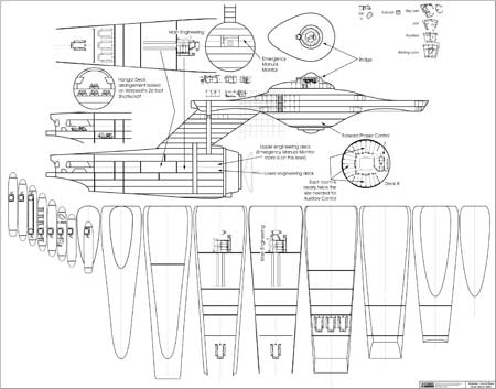
Another fan attempt at TOS deck plans

Discussion in 'Fan Art' started by Shaw, Feb 11, 2008.

Thread Status:
Not open for further replies.
  1. USS Mariner

    USS Mariner Rear Admiral Rear Admiral

    Joined:
    Jul 11, 2004
    Location:
    Homestate of Matt Jefferies
    I wonder...

    Wouldn't it be possible to build a replica of the forced perspective set (CG preferrably) and figure out it's "true" length by fiddling with the camera? That way, you would be able to see what it's supposed to look like.

    The main problem here isn't actually the set, but rather the actual cameras and lenses they used. Perhaps some of the guys from Hobbytalk would know.
     
  2. Shaw

    Shaw Commodore Commodore

    Joined:
    Feb 21, 2007
    Location:
    Twin Cities
    TIN_MAN-
    The image over at Star Trek History was the one that I used to modify my current back wall from MGagen's (using his as a starting point). While I'm still not sure where the force perspective ideal point is, long/wide shots like these are great for flushing out the additional details of the set itself.

    Tallguy-
    You're right in that the way the set was shot over the three season pretty much negates the effectiveness of the forced perspective. The only place I'm playing with the possible length is with the deck plans... for the clean up and scaling of the set plans I plan on attempting to illustrate the set piece as-was.

    I'll also be including my shuttlecraft interior plans (which I originally did for Starship Exeter) which show the set as built rather than an attempt to reconcile the interior with the exterior. I'm hoping that this type of stuff might come in handy with fan productions.

    Mariner Class-
    I recall that USS Columbia (aka uss_griffin) had done some reverse engineering that way at one point. Always something to look into.
     
  3. Harry

    Harry Captain Captain

    Joined:
    Feb 29, 2000
    A quick question... I know it's a long shot (and probably not very easy to do), but are you going to consider the weird and wonderful engineering sections we saw in TAS?

    Oh.. and what about that particular Jefferies tube Scotty once crawled in to repair the engines (I don't remember the episode name for some reason). There were some hints this particular tube may have been inside the pylon, or at least very close to the engines.
     
  4. Shaw

    Shaw Commodore Commodore

    Joined:
    Feb 21, 2007
    Location:
    Twin Cities
    I'll most likely not be addressing the TAS stuff, mainly because you just couldn't get any real idea about scale from the show.

    I was thinking about putting the horizontal Jefferies tube between the warp engine support pylons along the spine of the secondary hull.
    ___________________​


    I think this will most likely be the last updated scratch sheet for a while, and as such I put a lot of what I had on earlier sheets on this one.


    The primary additions to what I had down before are the deck levels of the secondary hull. So between this sheet and this one from awhile back, I think I've touched on (at least in some small way) every deck except deck 7... which should house sickbay. The only real change that I know I'm going to apply to the earlier primary hull decks is Cary's suggestion to break up the turbolift ring on deck 5 so that part of it is on deck 6.

    While messy, I think what I've put forward should sort of illustrate where I was planning on going with this. The key elements that I want to address at this point are:
    • Placement of most (if not all) seen areas of the ship.
    • Plausible accommodations for 430 crew members.
    • Space for 4 shuttlecraft.
    • Space for Impulse Engines (assuming that the outlines on the rear of the primary hull are the approximate area needed for them).
    Leaving other areas open, I hope that there is enough room for other things that were mentioned but not seen (like 14 science labs).

    In addition to plans based on my arrangements, I'll also create a document with empty deck levels and examples of rooms (with variations to help with placement at different radial distances in the primary hull) so that people can really go to town with their own ideas. :thumbsup:
     
  5. Reverend

    Reverend Admiral Admiral

    Joined:
    Jul 31, 2002
    Location:
    UK
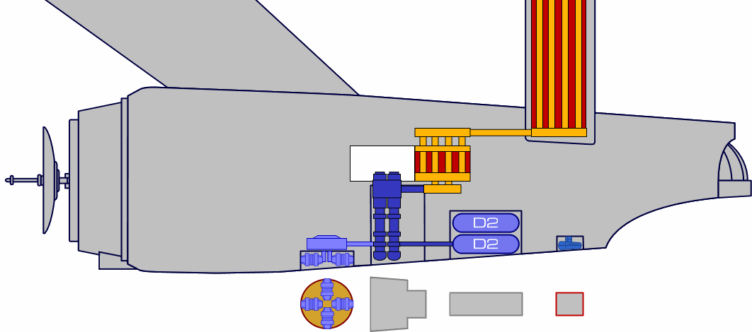
    Not sure if this has been addressed already (I'm far to lazy to read through 10 pages!) but I'm wondering about the two different engineering sets that we've seen and if they were the same room before and after a refit or if they're two (nearly) separate places?
    Assuming you've got the scale correct, there seams to be room at either end of the BGCs (Big Giant Conduits) to fit in both facilities. like so.
    [​IMG]


    I know it's not the point of this thread but I can't help speculate the function of the BGCs. Until now I always just assumed they were the bottom end of the warp plasma conduits, sort of like this.
    [​IMG]
    Now I'm wondering if they're actually the deuterium injectors, or maybe the plasma coolant tanks? I'd be interested to know how Rick Sternbach might assign function to some of these features, given his influence on Trek Tech since TNG.
    *rubs magic lamp and feeds a really hot cup of tea into the Sternbach Improbability Drive*
     
  6. Redfern

    Redfern Rear Admiral Rear Admiral

    Joined:
    Sep 28, 2006
    Location:
    Georgia, USA
    Hmm, now that's an interesting arrangement! If I'm "reading" this diagram correctly, are you suggesting the engineering section we saw in the first season was a facility aft of the "Tubes" with the grille facing towards the bow and the complex seen in the second season onwards is foward of the same "Tubes" with the grille facing towards the stern, both existing at the sme time?

    Never have I ever considered that, but it's certainly no more crazy than some of the other layouts presented over the years. Now I have this mental image of someone being "cute" and shouting through the grille to get the attention of someone in the other room without bothering to use the intercom or a communicator.

    Sincerely,

    Bill
     
  7. Shaw

    Shaw Commodore Commodore

    Joined:
    Feb 21, 2007
    Location:
    Twin Cities
    Ya know, ever since I first saw something like that put forward on April's deck plans, it has really seems like the perfect solution to a lot of consistency issues.

    For example, in Doomsday Machine the engine room starts out with the island, but in some of the later scenes it is gone and replaced with a control panel. I know that some of that is reused footage from season one, but there are other examples similar to this throughout the series that could totally be smoothed over by that arrangement.

    The other idea I like is aridas sofia's positioning of similar rooms dedicated to either warp or impulse engines.

    And that really is why I want this to work out as a platform for people to tryout and share different ideas. April and aridas are both very talented artist, but that shouldn't be the barrier to entry for sharing concepts.

    I also like your ideas for what may be along the base of the secondary hull given the markings down there! :thumbsup:
     
  8. Shaw

    Shaw Commodore Commodore

    Joined:
    Feb 21, 2007
    Location:
    Twin Cities
    A little off topic, but I was doing overlays of the image that Reverend posted and an early cross section by aridas sofia, and I'm a little relieved that the general outlines come pretty close to matching. The outlines that I'm using for the ship's exterior are based on the preliminary work I was doing on a study of the 11 foot model. As such, I had been avoiding comparing them with any other plans to keep from contaminating them with any preconceived ideas. So this marks the first (indirect) comparison so far and I'm quite happy that I'm not way out in left field on this.
     
  9. MGagen

    MGagen Fleet Captain Fleet Captain

    Joined:
    Feb 28, 2003
    Location:
    Crucis Court, Trans-Coal Sack Sector
    I don't follow. The conduits have to go somewhere. You're putting them in the drawing. The net effect on "blank space" is the same where ever you put them...

    I'm sure the forced perspective effect was "eyeballed." I doubt there is any one ideal spot. But the angle change on the foreground conduits that I pointed out implies that they planned to be "looking up at them." The change in angles is just like what you'd get with a wide angle lens tilted upward from the horizon. I can probably knock together a quick 3D model with 45 degree angles throughout that would show roughly the same effect.

    Going back to my previous post, I'd like to hear your thoughts on my observation about the rearmost conduits giving the best impression of the "true angle" of the structure; and about Jefferies explicit siting of the engineering room in his Phase II plans.

    M.
     
  10. Shaw

    Shaw Commodore Commodore

    Joined:
    Feb 21, 2007
    Location:
    Twin Cities
    But once they disappear into the housing, can anyone really be sure where they go after that? Other than the visible conduits and the housing seen on screen, I'm attempting not to make too much more of what happens in the unseen areas in this project. For all we know, maybe the diamond shaped loop is all that there is... and they move (whatever they are moving) around in a circular pattern.

    So in that way, I'm trying to avoid placing in concepts (even ones I favor) that might discourage others from attempting other possible solutions they could come up with.

    Yes, you are most likely right about the correct angle. If the foreground conduits are intended to display another perspective angle, then yeah, the furthest back set would be the ones to go off of for the true angle.

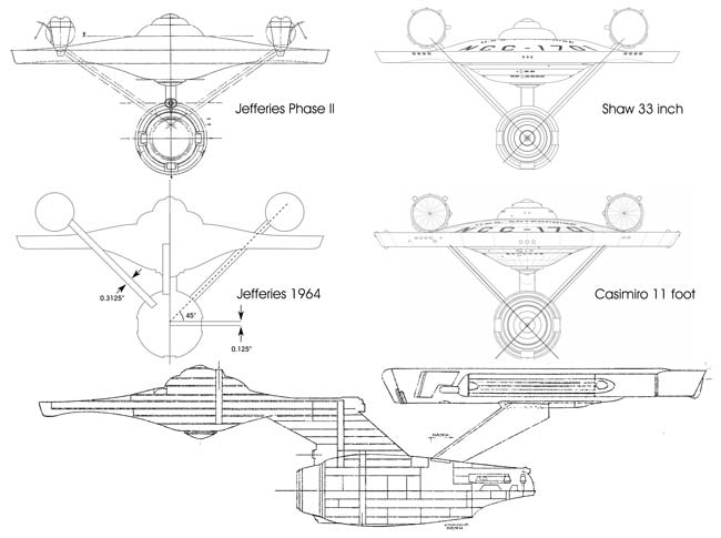
    As for the Phase II engineering location... I have to admit that I had never really looked into that. I've taken into account the size of the hangar deck and the relative deck heights, but I'm not really sure where Jefferies intended engineering to be.

    The two problems I have with applying the Phase II plans too much towards engineering have to do with (1) the new angle of the warp pylon supports, and (2) the large bay and hatch placed between where those supports attach to the secondary hull.

    [​IMG]

    So it is one of those things where I'm not quite sure just how much of the internal arrangement was altered for the new warp engines in Phase II.

    What it reminds me of is the upgrade procedures done on aircraft carriers. In order to get the engines in and out, large sections of the decks between the flight deck and the engines have to be cut away and later refitted into place. Considering that the support pylons attach at very different points than they did originally, I would think that that type of cutting might have been done for the upgrade.
     
  11. MGagen

    MGagen Fleet Captain Fleet Captain

    Joined:
    Feb 28, 2003
    Location:
    Crucis Court, Trans-Coal Sack Sector
    Jefferies' Engineering location on the Phase II drawings actually comes from the legend:

    It shows the level of detail he went to in thinking through his design.

    You have a good point about the interior configuration of Engineering being affected by the new pylons. The extreme high-bay on his drawing probably was going to contain something like the vertical doo-dad we saw in TMP. No doubt Main Engineering would have looked totally different from the series had he gone through with production design.

    But the high level of agreement between his Phase II and TOS section views has always suggested to me that the later drawing is the Rosetta Stone for interpreting the less detailed TOS drawing that has come down to us. And since Jefferies viewed the ship as a true refit, it's reasonable to assume the new engineering section was an expansion in the old space.

    And the old one fits so nicely into the Phase II area...

    At any rate, keep up the good work. I am following your progress with interest.

    M.
     
  12. Captain Robert April

    Captain Robert April Vice Admiral Admiral

    The Phase II secondary hull might've also been a whole new unit with a similar, but not exact, interior layout as the original hull.

    The only section he explicitly stated would be the same was the saucer, and even that got some alteration, albeit minor by comparison.
     
  13. Captain Robert April

    Captain Robert April Vice Admiral Admiral

    Flip those engine rooms around and you come pretty close to the layout I came up with about, ooooh, five years ago. :D
     
  14. Rick Sternbach

    Rick Sternbach Fleet Captain Fleet Captain

    Joined:
    Feb 11, 2002
    Well, I'd say it's an interesting way to shoehorn the sets into the Engineering hull and connect up some matter and antimatter supplies, etc. If as some believe the actual boom reaction doesn't happen until the nacelle interiors, then all of the gear in the Engineering hull could be for some type of deuterium pre-heating and antimatter distribution and mag-contained stream alignment. If, on the other hand, the reaction takes place in some channels or chambers under the set floor, then the crisscrossed forced-perspective red PTCs behind the grille on the stage actually delivered hot-hot-hot plasma to the nacelles. Naming the equipment in either case is pretty simple, it's similar to what's in the TNG TM, it's just the placements that might need rearranging.

    Rick
    www.spacemodelsystems.com
     
  15. Captain Robert April

    Captain Robert April Vice Admiral Admiral

    The one thing that tells me that those tubes don't run to the nacelles, or at least makes it problematical, is that dilithium crystal doohickey in the middle of the room (which also tells me that the matter/antimatter boom happens under the set floor and not up in the nacelles).

    Simpler to assign some other function to those things. Like, oh, say, a power transfer manifold to send power to the rest of the ship... :D
     
  16. Reverend

    Reverend Admiral Admiral

    Joined:
    Jul 31, 2002
    Location:
    UK
    That's the basic idea, yes.

    I wouldn't put too much faith in that graphic of mine, it was done off the cuff several years ago for a similar discussion over on the Flare Forums. Just my view on how the visible components might relate to each other. ;)
    The ship itself though should be reasonably accurate though, I think I based it on one of Sinclair's blueprints.


    If memory serves the Dilithium is located in engineering, (appeared in the evil antimatter universe matey bloke episode I think) so the reaction really does have to take place in the secondary hull. So that would indeed make the glowy red wotsits the warp plasma conduits/eps manifold type of thing. Roughly equivalent to the Spock killing "mains" room from TWOK, hence all the shielding.
    The exact angle of big pipes in relation to the exterior pylons wouldn't really matter since as I preposed in that diagram they could easily change direction the instant they go out of sight to fit in with whatever arrangement you like.
     
  17. Data Holmes

    Data Holmes Admiral Admiral

    Joined:
    Apr 21, 2001
    Location:
    zone.33 lounge at club Planet Noir
    The dilithium is what they use to convert what ever the warp engines up the the pylons make into electrical energy to power the ship... so it's revers what is shown in TWOK, with stuff coming down from the nacelles
     
  18. Captain Robert April

    Captain Robert April Vice Admiral Admiral

    Huh? What show have you been watching?

    Here's the sequence of events in a life of a warp engine:

    Matter and antimatter meet and go BOOM.

    That BOOM is run through a dilithium crystal, turning it into a BOOM!!

    That BOOM!! is then sent to the warp coils, so that they can generate the warp field, which makes the ship go really really really really fast.

    Any questions?
     
    Last edited: Mar 9, 2008
  19. Shaw

    Shaw Commodore Commodore

    Joined:
    Feb 21, 2007
    Location:
    Twin Cities
    See, this is the type of thing I was wanting to avoid... I mean I could introduce a modified version of an espresso machine diagram and as long as I kept a straight face there is a good possibility that some people might buy it as engine schematics of a starship.

    We (people of the 21st century) are, in the end, talking about technology of the 23rd century. Even with tremendous intelligence, a strong background in physics and mathematics, a pretty clear idea of what we want for an end result, and a lot of creativity... are still stuck in the 21st century and limited by this.

    The odds are that even if (and this is a big if) warp drive is around by 2265, it'll look about as much like our ideas as a modern airplanes design looks like Leonardo da Vinci's drawings of a flying machine from the early 16th century.
     
  20. TIN_MAN

    TIN_MAN Fleet Captain Fleet Captain

    Joined:
    Aug 26, 2007
    I think there's a happy medium somewhere? While I can understand why you don't want to get too technical in the 'made up' details, still, it seems even with the sets and models of TOS as we have them, and how they were postulated to work onscreen, there's going to be a need to give some thought as to how it might work and all fit together? After all, this is not only part of the fun of a project like this, but will ultimately determine the basic placements of the elements we do have to work with?

    P.S. while we're more or less on the subject of future technology, has anyone checked out Thomas Beardons' website on scalar wave physics and the unified field? For those interested in such things, he has some fascinating ideas on how to engineer 'warped' space and even speculates on how scalar waves can be used to make the phasers, tractor beams and deflector shields of Star Trek, a reality in our life times!
     
    Last edited: Mar 9, 2008
Thread Status:
Not open for further replies.