• Welcome! The TrekBBS is the number one place to chat about Star Trek with like-minded fans.
    If you are not already a member then please register an account and join in the discussion!

Refit/1701-A - 3D Model, Full Interior

For the turbolifts in the rec dec, I always imagined they came in horizontally at second level and lowered themselves down to the first level for folks to get in and out... There's clearly no way in can just be a vertical pass through, but I think they have to be turbolifts given the design of the tube there.
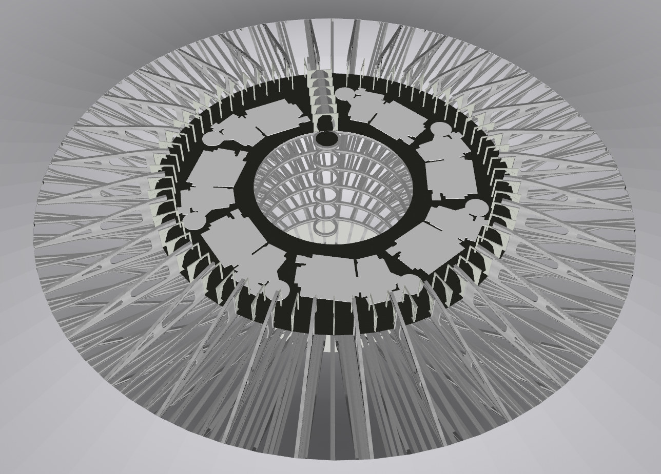
I was toying with doing exactly that, but the issue I have there is that the tubes at that scale are only a little over 4ft in diameter. They'd have to be literally double that to serve as a turbolift.
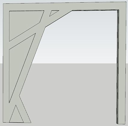
What I 'might' do is have a go at making the room a true rectangle instead of it being wedge shaped to fit the lines of the hull structure. That would make the gallery area an extra 3m (9ft) wider, but I think even then it wouldn't be quite enough to comfortably fit usable turbolifts.
 
Your work here is absolutely brilliant. I love the engineer's approach to making certain everything fits and is functional. I'm certainly looking forward to upcoming installments! Thank you for for all your time, dedication and hard work!
 
I've been tinkering with D Deck this evening in the hope that I could bang out some rooms, but as always interesting challenges are plentiful. The first issue was the shape of Kirk's quarters and the location of the connecting corridor, because the door is located on the outside edge of the curve. However, looking back at TWOK there's actually a scene about 35 minutes in where Kirk leaves the turbolift to go to his quarters, and in front of the lift door is a straight corridor. It turns out this matches the deck layout perfectly, because to get to the door of Kirk's quarters you actually do need to use a corridor that leads away from the lift doors as below (sucks for you if your quarters are on the farthest side of the deck :P ). I should be able to fit 7 Kirk-style quarters on D Deck, but I also need to fit a phaser control room in there too. That'll probably have to go in the middle, and I'll have a jefferies tube going all around the outside to access/repair/maintain the phaser hardware.
d_deck_1.PNG


Another issue I've been having is getting the circular corridors right, because despite a lot of searching I can't find *any* reference material for them. I've eyeballed it as best I can as per the second archway in the example below, but I'd like to compare it to a legit source. As far as I can tell, when the sets got overhauled for TNG they changed these corridors to have straight walls on both sides, so what I've done is taken the 96" width of the TNG set and added my best attempt at the angled parts. I'll beautify and smooth them out a bit later.
arches_example.PNG

I've got enough done for another VR video now, so I'll sort out the textures in Unreal Engine and record a new video over the weekend.
 
Would there be enough headroom at the forward, port, and starboard sections of D-deck on the outside of the exterior corridor to fit in a phaser control station? I should think it would be possible to fit a decent-sized room that would have a cross-section similar to the nose section of a shuttlecraft in the sloping outer area between the structural supports. Hopefully, that makes sense what I'm trying to say.

For the corridors, you could try referencing Mr. Scott's Guide to the Enterprise. It has a section and elevation views, along with a scale. I believe Shane Johnson did those drawings based on the actual sets, so it should be fairly accurate.
 
Arg. I don't have access to the corridor set pieces I built while I'm at work. I have my older ones that are based off Mr. Scott's Guide to the Enterprise.

Either way I'll work something up to share with you Dan, if you'd like. I love what you're doing with this!
 
Arg. I don't have access to the corridor set pieces I built while I'm at work. I have my older ones that are based off Mr. Scott's Guide to the Enterprise.

Either way I'll work something up to share with you Dan, if you'd like. I love what you're doing with this!

That would be awesome, thanks :)
You've also reminded me that I do actually have Mr Scotts Guide around here somewhere, I shall have to dig it out :D
 
Would there be enough headroom at the forward, port, and starboard sections of D-deck on the outside of the exterior corridor to fit in a phaser control station? I should think it would be possible to fit a decent-sized room that would have a cross-section similar to the nose section of a shuttlecraft in the sloping outer area between the structural supports. Hopefully, that makes sense what I'm trying to say.

That's a good idea, and it could also have the jefferies tube entrances on either side too. I'll see how much headroom there is available :)
 
Probably mentioned upthread, but aren't all these set proportions and corridor detail dimensions discussed in-depth on the Set Blueprint Exchange thread?
 
Probably mentioned upthread, but aren't all these set proportions and corridor detail dimensions discussed in-depth on the Set Blueprint Exchange thread?
A lot are yeah, but there are a few bits and pieces which have less source material available. I'm a big fan of the Blueprint Exchange, so I've spent quite a bit of time going through it :P
 
A lot are yeah, but there are a few bits and pieces which have less source material available. I'm a big fan of the Blueprint Exchange, so I've spent quite a bit of time going through it :P
Ok. I thought they'd pretty thoroughly covered the K-beam issues. Maybe not.
 
Ok. I thought they'd pretty thoroughly covered the K-beam issues. Maybe not.
Yeah, this type of K-beam is well covered (@Redgeneral did some awesome work): https://www.flickr.com/photos/99878876@N02/15632727204/in/set-72157644597012434
It's this other type I was struggling with:
k-beam.JPG

The width and height are sorted, but I've been looking for some source material on the angled pieces. Mr Scott's Guide has a cross section, so I've been using that. Apologies to the contributors on the Blueprint Exchange if I've overlooked something! :)

Looks like you've got a good handle on that! Sorry I didn't get back to you. It's been... well an interesting half week between work and home. lol
 
Looks like you've got a good handle on that! Sorry I didn't get back to you. It's been... well an interesting half week between work and home. lol
Hey no worries, life outside of our Trekkieness (is that a word?) always has to come first. Hope things get better for you :)
 
Never mind putting me in a home when I get old, just slap some VR goggles on me and let me live out my days in here.
 
That never occurred to me but you're right, there's no way those could be lifts, even though the design motif is nearly identical to how the lift appears down in the secondary hull when Kirk first arrived.

Perhaps the other tubes pull double duty as turbo shafts and lighting tubes while these ones are only lighting tubes?
 
Yeah, this type of K-beam is well covered (@Redgeneral did some awesome work): https://www.flickr.com/photos/99878876@N02/15632727204/in/set-72157644597012434
It's this other type I was struggling with:
k-beam.JPG

The width and height are sorted, but I've been looking for some source material on the angled pieces. Mr Scott's Guide has a cross section, so I've been using that. Apologies to the contributors on the Blueprint Exchange if I've overlooked something! :)
I did this to estimate the differences once. I think I goofed up the highest point, which might be at the same height.
15681370094_0fcd4c19ac_o.png
 
I've been working on the bridge a bit, and I'm happy to report that everything is fitting perfectly so far (although it's very snug). The bridge is 37' wide internally, and the turbolift internal diameter is 8'. The upper rim of the turboshaft did breach the curve of the hull at first, but making the top of the shaft domed solved that problem. The turbolifts don't line up with the lumps on the upper hull of course, so what I'm going to do is make them access panels for the turboshaft hardware, or perhaps connection points for an external emergency power source? Something like that.

bridge_wip1.PNG

bridge_wip2.PNG
 
If you are not already a member then please register an account and join in the discussion!

Sign up / Register


Back
Top