I am so looking forward to having this model and I am happy to be apart of the team now.
-
Welcome! The TrekBBS is the number one place to chat about Star Trek with like-minded fans.
If you are not already a member then please register an account and join in the discussion!
You are using an out of date browser. It may not display this or other websites correctly.
You should upgrade or use an alternative browser.
You should upgrade or use an alternative browser.
USS Grandeur - One... More... Time!
- Thread starter Vektor
- Start date
... but I'm a pretty damned good engineer. I've been through this sort of thing on many design programs. And as a result, I've developed a basic "standard practice" that I use on everything.
Before I make any physical elements of any kind, I create a very detailed "skeleton" made up of datum planes, datum axes, datum points, and sketches (never intended to be seen in the final model). I then build my geometry using those as references. That avoids the very problem you're encountering now.
If dealing with habitable spaces, I generally create datum planes to reflect the floor and ceiling of each individual deck. I create sketches (on individual datum planes) reflecting basic structural elements. It's a long and involved process but it's invaluable... because you already have geometry (which will never be visible in the final model) which you can reference as you create every downstream feature.
The problem with this approach is that you lose the ability to "massage" certain elements... you're pretty much tied into the general layout you create up-front. But if you do that layout in a parametric fashion, you can then "tweak" the layout in those datums and sketches and everything else downstream will update "automagically." (Or "most everything" anyway.)
Cary, I'm fascinated by what I think you're talking about here. Could you go into a bit more detail about these datum planes you use and your parametric approach? Pictures, videos, and personal, one-on-one hand-holding at your expense are all welcomed. Thanks!
Well, I don't want to "hijack" Vektor's thread here so I'm just going to post once on that topic... if you want to pursue this further, we can create another thread or we can go "private."Cary, I'm fascinated by what I think you're talking about here. Could you go into a bit more detail about these datum planes you use and your parametric approach? Pictures, videos, and personal, one-on-one hand-holding at your expense are all welcomed. Thanks!
I'm going to use my "Bonaventure" model as a reference. But this approach follows generally.
Unlike with some other vessels, my work on the Bonaventure has the entire hull constructed as a single "part." On more complicated efforts, I make assemblies of multiple parts. (This version of the Bonaventure was never intended to be a "complex" model, so much as a "what if" exercise... just to see if I could make the animated-series ship look good, and look real, and make a degree of sense to me.)
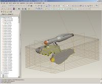
Here's a cross-section of the Bonaventure. You can see the various datum planes reflecting my floors and ceilings (those are normally hidden) The "model tree" at the left is a sequential display of what is created in what sequence... I'd usually cut that part of the UI out of the view, but it's worth seeing it here... the point is that I created those (reflecting my floor and ceiling surfaces) before ANYTHING else, and use them as a reference as I create everything else.
(click the thumbnail to see the full-size image... don't want to make the thread load more slowly than it should for images unrelated to Vektor's work!)

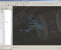
Now, virtually all geometry in ENGINEERING applications (as opposed to "artistic" applications... ) is done using sketched 2D sections in one fashion or another. Here's a simple example... you can see the parametric sketch which defines the rotated cross-section for my "main sensor/deflector dish." An axis exists in the part (created separately) and I used that as the centerline of my sketch... drew 1/2 of the shape, and revolved it around that axis to create a solid (not "surfaces" like most 3D graphics programs do, but they have similar functions that just do surfaces).

You'll note that the sketch is dimensioned, of course... I can create those dimensions simply (as seen here) by entering a value into them directly... or I can have complicated mathematical algorithms. Most commonly, simpler equations are used, though... things like "the diameter is 1/10 of the length" or conditional things like "replicate this pattern by X times... with X being 5 if the length is less than or equal to this value, and 8 if X is greater" or so forth.
It's almost like working with a programming language (and yes, I can even implement input routines or conditional loops or any other programming tool you're accustomed to, so that the model regenerates itself "on the fly" based upon my input.
Now, you can any geometry referencing any other geometry, basically... so I sketch basic shapes and guides and so forth before I start my physical modeling, most of the time. Since virtually EVERY "physical feature" is based upon sketches anyway, it's only reasonable to have certain "root" sketches that everything else follows from.
SO... after working out he basics, and figuring out generally how many decks I want it to be, how long I want it to be, where certain features need to be, etc, etc... I use that to create my basic... well... "skeleton" for the model. And I use those features to define later features. For instance, the centerlines of my nacelles are defined by a distance from the centerline of the secondary hull and an angle from the centerline of the secondary hull (well, actually from the axis which I created to represent the centerline of my warp reactor assembly... but you get the idea).
What it means to be "parametric" is that we're dealing with ALGEBRA rather than with "locked in stone numbers." I can easily adjust the angle or the distance simply by altering the value of that particular dimension, and "regenerating" the model.
Now, for instance... I created a parameter up-front called "floor-to-ceiling_ht." I established the distance upwards from the deck to the adjacent ceiling. And I established another parameter called "inter-deck-thickness." So, when I started creating my series of decks, instead of typing in a value every time, I simply assigned each plane's location as being offset from the next one by one of those two variables.
If I then decide to change my deck-to-deck spacing to a smaller number, I only need to adjust that one variable and the whole model updates as a result. Granted, some features may fail (like rounds whose original value may result in them intersecting some feature that they didn't intersect before, due to the "respacing") and I may need to "tweak" them a bit to get them to work again... but it's a LOT easier than rebuilding from scratch... or individually moving around NURBS surfaces!
Anyway... that's a basic primer on the differences between "engineering CAD" design (3D, but driven in large part by 2D elements existing in a 3D world) and "rendering" work (which is usually a bit less "dimension-oriented")
My "work" flow is all about the CAD software, of course... but for "hobby" work, I've found that I like doing the model in CAD first, then exporting it to some other software (I've been using Maya 6 for a long time and am pretty good with it... PROVIDED that I can get the damned model to translate in as NURBS!) Once in there, it's divorced from the original, parametric model... it's just a normal Maya model, and can only be edited using the built-in Maya toolset (which is extensive but totally non-engineering-related) The great thing about Maya is that I can do things with rendering that no CAD package every could... like my "real-time flaming bussard collector" effect I have in my "Vega" warp nacelles or the "vorlon skin" morphing exterior radiator panels on the same nacelles... both of which can be seen here...


Last edited:
Amazing. You come much closer to actually building your starships than I think most people do. I do most of my work in Blender, which definitely isn't an engineering application (although I've used it to design real-world, customized furniture and a few gadgets). I'm trying to think of a way to incorporate elements of your approach into my workflow, but short of programming my designs in python or using proper CAD software, I'm not sure it can be done.
What do you do about designs where deck height isn't consistent? I'm presently building a model that's based on the Soviet anti-sub cruiser Moskva, and the decks on that ship go all over the place. How would you compensate for something like that with your datum plane approach?
Maybe we should, in courtesy to Vektor, break this out into a general discussion thread about modeling techniques, if you're so inclined. Either way, thanks for the insight, this is really neat!
Well, it's been a crazy week and I haven't gotten very far on updating the actual model; however, I did make some progress on the new gridline templates for the upper and lower surfaces of the primary hull...


Neither of them are finished but the top is fairly well along and I have a good idea of where I'm going with the bottom. The radial gridlines are now properly aligned on both top and bottom and also line up pretty well with the other major features.
By the way, these templates were traced directly off the model as editable splines within 3ds Max, then exported into PhotoShop for compositing with my usual background.
 Lookin good, Vek!
 I might add that it would help the Chief if, when you are done with the new lines for the top, send a pdf/dxf of them for him to pull into his vectorized schematic. He's working on the LCARS for the Engineering pooltable right now. Thanks, Vek.
Lookin good, Vek!
I might add that it would help the Chief if, when you are done with the new lines for the top, send a pdf/dxf of them for him to pull into his vectorized schematic. He's working on the LCARS for the Engineering pooltable right now. Thanks, Vek.
Your friendly neiborhood Ops Officer could use it as well for the tech manual.
I've been doing some interesting things to the Grandeur. The entire arrowhead-shaped plate on the top of the primary hull has been rebuilt using Sub-Ds, with the secondary deflector and the aft wedge-shaped cutouts included in the base mesh:

And here is two iterations of NURMS subdivision:

And finally, the rendered product:

There's a lot of other stuff going on as well but I'm keeping that close to the vest for now. I should have at least a couple more renderings to show this weekend, however.

And here is two iterations of NURMS subdivision:

And finally, the rendered product:

There's a lot of other stuff going on as well but I'm keeping that close to the vest for now. I should have at least a couple more renderings to show this weekend, however.
How do you keep the edges of the cutouts following the arc of the saucer? Vertex weighting?
WEEEEEeeeeee! Woot!
Your work amazes and inspires me!
Please sir, I humbly beg you to take a look at my work:
http://trekbbs.com/showthread.php?t=65650
Your work amazes and inspires me!
Please sir, I humbly beg you to take a look at my work:
http://trekbbs.com/showthread.php?t=65650
Vektor... I'm speechless. Well, besides the capacity to tell you I'm speechless, but... wow.
great work. i like it. i wish i could do stuff like that. looks so complicated.
Does anyone ever just want to reach out into their screen and just hold what we see?
Nah ... I want to keep getting closer! I want to pry open the doors and start looking around the inside. I want to dig into the circuits behind access panels, and read the tech manuals that must be displayed on countless screens within. And when I'm done, I want to come out with a phaser and tricorder stuffed down my shorts as souvenirs of my exploration.
Vektor's work carries a weight that tricks a part of my mind into believing this thing is real. Ever bump, every gizmo, every doo-dad on the hull piques my curiosity ... what does that do?!. I'm not looking at a random mishmash of parts that fit together to make a model, I'm looking at a starship!
Vektor....you so need to make a tutorial. God I want to pick your brain. I went to school for two years and have been 3D modeling professionally(more or less) for several years....and I still suck compared to you. 

Vektor....you so need to make a tutorial. God I want to pick your brain. I went to school for two years and have been 3D modeling professionally(more or less) for several years....and I still suck compared to you.
I remember when he was going to make a tutorial for his TOS warp nacelle caps.

Similar threads
- Replies
- 482
- Views
- 61K
- Replies
- 192
- Views
- 29K
If you are not already a member then please register an account and join in the discussion!


