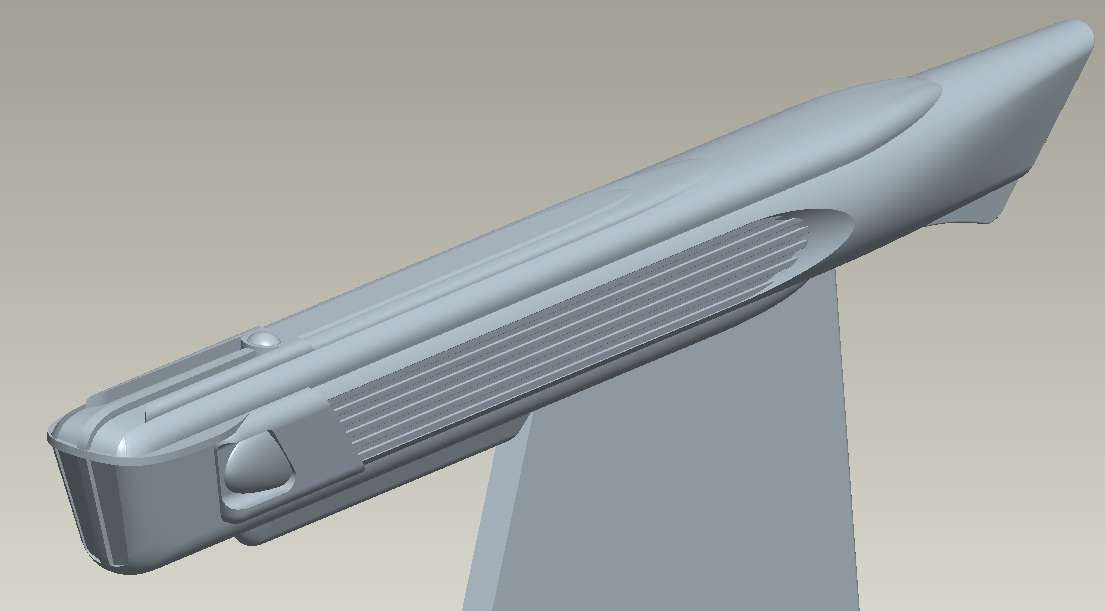
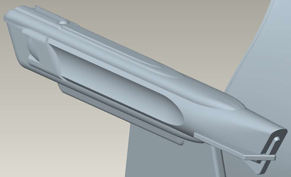
I like the nacelles. They have the chubby, beefy look I intended for the LN-65.
As for the bridge not working with the later sets...
You've caught me.

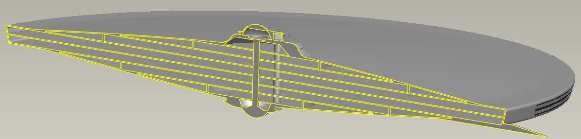
The low height areas at the saucer's outermost regions are for atmospheric and other life support recycling as well as farm areas for fresh fruit and vegetable production, and storage. However, the entire saucer is conceived as a semi-monocoque design, with the saucer skin and its various field geometries providing part of the structure, but part being supplied by a hollow, trunk structure connected via the thin deck structures to complex ribs that sit under the radiating force field grid at the hull surface. You can see the ribs in my cross section of Avenger, here:
http://www.cygnus-x1.net/links/lcars/blueprints/general-plans-uss-avenger-class-sheet-5.jpg
This will also show you the intended deck heights relative to the deck thckness and the saucer edge. The idea was that the gravitational plating in those decks and the antigravitational force field grid were in a constant tug of war that acted kind if like a suspension span on a bridge, and formed the field component of the "semi" monocoque structure. This gravity tug of war also was meant to be a big determinant on the warp dynamics of the ship-- its relative ease using its other gravity-antigravity generators -- the nacelles -- to manipulate the surrounding spacetime fabric.
Hi Aridas,
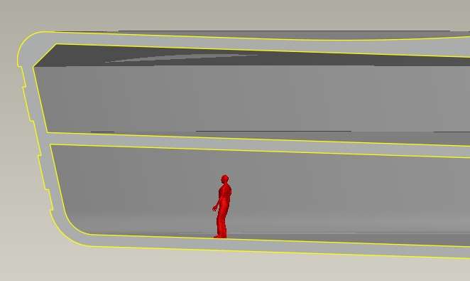
I'm still bugged by the deck spacing. Basically, to get the internal structure you've shown me, the deck heights are 2.638m (or 8' 7-7/8"). That's a pretty low ceiling height, far less than has ever been seen in any incarnation of Trek, except for shuttle interiors and Jefferies tubes.
Basically, a 6' tall guy can reach up and put his bare hand on the ceiling, flush, without stretching.
And the windows at the p-hull edge still don't line up properly with eyelines. Realistically, the primary hull needs to be thicker, I think... to give the two decks proper "window eyelines". But that does change the appearance a bit.
(FYI, I know that this is also derivative from the TMP Enterprise... which leads me to conclude that the size of the TMP Enterprise is also a bit on the low side to make things fit properly. Does anyone know what the actual physical height of the corridor sets for TMP was?)
EDIT:
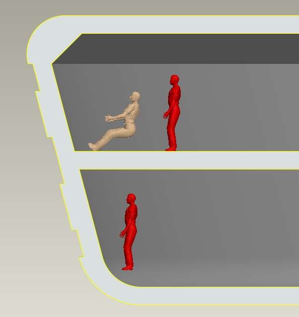
Now, given this deck spacing, the deck arrangement you intended is possible, of course. Decks 1 and 2 are different heights, but everything else matches acceptably, as seen here:
Basically, the windows on the upper rim row only make sense if they are "seated eyeline" windows, while the lower rim windows only make sense for "standing" viewing. But I can live with that, I guess.
Now, for a ship to have as-seen-on-screen sets, the ceilings should be ~9' 6" tall, not 8' 7" tall. This basically requires a full upscaling of the model to 110% of your listed size numbers.
Then again, for my TOS Enterprise, I found that 947' didn't work, and I had to upscale to 1067'... or 113%
Now, I know you based your ship on the TMP ship dimensions. However, as it turns out, I think we've also seen that TMP-era sets don't really work ideally in the model at the scale given, do they? I strongly believe, for example, that the bridge I've got here is literally too small to hold the set we were given in TMP (much less later-era ships).
SO... I'm inclined to go ahead and do a full 113% upscaling here, just as I did for the TOS ship. I'll apply this universally, and I'll see how things work out.
The secondary hull windows will upscale appropriately as well... but I have no problem with giving thicker deck structures in that region, the "neck," which is a principle load-bearing element. I'll try to keep the 9.5' ceiling height, however.
Your thoughts?
Edit 2: Well, the upscaling works passably well.
With the increased scale, I was able to get a full "as seen on-screen" ceiling height (2.9m, or 9' 6-5/32"). I kept uniform thicknesses for both the hull and the decks for simplicity's sake... 0.44m, or 17-5/16".
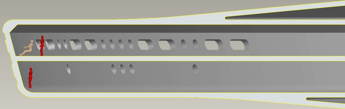
Not IDEAL, exactly... the upper windows still only make sense for "seated viewing" but at least they work a bit better. The lower level requires a step-up to get to eye-level for the windows, but there are a only a few of those viewports, relatively speaking.
The ideal is really to go for a much larger saucer than I've done here... See, even with the upsized scale the window centerlines are only 2.280 meters (7' 5-3/4") apart, and they simply won't line up on the existing decklines. Of course, on the pre-resized version, they were only 2.024 meters (about six and a half feet) apart!
Ideally windows should be spaced evenly between decks, so that the eye-level is uniform at each deck. If we assume the decks are spaced as seen on-screen (2.9m, or 9.5' plus some undefined interstitial space... let's stick with 0.44m because ~18" seems reasonable to me)... then the windows eyelines should be 3.34m apart.
That means that for the Ariel to keep it's as-drawn shape and to also match up with what was seen on-screen (on the TMP ship), with these windows not requiring steps-up or seated viewing, you'd need the ship to be upsized to 165%!
My solution is to put these into high-bay "lounge" areas, instead, and I'll keep my new sizing. The windows will be viewable from a performated-metal-type (and very thin!) viewing platform above (think of a catwalk) and a step-up platform below. This way I can keep the working deck structure, due to the resizing I've got, to match your intention, and still have the windows make some form of logical sense.

")

")

