-
Welcome! The TrekBBS is the number one place to chat about Star Trek with like-minded fans.
If you are not already a member then please register an account and join in the discussion!
You are using an out of date browser. It may not display this or other websites correctly.
You should upgrade or use an alternative browser.
You should upgrade or use an alternative browser.
Refit/1701-A - 3D Model, Full Interior
- Thread starter DanGovier
- Start date
")
Just found this thread. Amazing and stunning work you've managed to accomplish. I'm not sure what references you're using but this may help you with the space issues you were having with the bridge/turboshafts and the VIP window ports:
http://www.trekbbs.com/threads/u-s-s-enterprise-how-many-decks.276564/page-2#post-11415850
http://www.trekbbs.com/threads/u-s-s-enterprise-how-many-decks.276564/page-2#post-11415850
Wow look at this thread all covered in dust... I've had a lot going on at work these past few months, with redundancies and other bits and pieces going on. The upside is, I will soon have a lot of spare time on my hands and I intend to pick this project up again. Watch this space!
Wow look at this thread all covered in dust... I've had a lot going on at work these past few months, with redundancies and other bits and pieces going on. The upside is, I will soon have a lot of spare time on my hands and I intend to pick this project up again. Watch this space!
I'm definitely looking forward to seeing you continue this.
I'm back!...like almost an entire year later...
I've been itching to get back into this project more and more lately, and I think my life has finally calmed down enough that I'll have enough free time on my hands to get stuck into it again. One small issue however, at some point along the way I lost my sketchup file... but rather than treating that as a disaster, I'm instead taking it as an opportunity to do things better and start again with a more solid foundation.
I'm already getting up to speed:

I've been looking at a lot of photos of various large submarines being dismantled, with a view to using that as a baseline for the structural design work. I figure that even with better materials and such being available a couple of hundred years from now, the laws of physics won't have changed and we'll probably still be building structures in a similar-ish manner.
I'm not sure why, but things are seemingly fitting better than they did last time. For example, the windows around the saucer rim almost make sense now... at least the upper windows are at eye level when you are sitting down at a table, and the lower windows are almost head height when standing. Plus, both the upper and lower phaser turrets on the saucer fit very nicely at mid-deck height.
The new model is almost exactly 305m long, and I'm sticking with 2.43m (8') high decks with 30cm thick floors. The outer hull i-beams are mostly 40cm thick for a bit of added strength. I'd love to run the numbers through a physics simulator to see just how strong it is :P
I've been itching to get back into this project more and more lately, and I think my life has finally calmed down enough that I'll have enough free time on my hands to get stuck into it again. One small issue however, at some point along the way I lost my sketchup file... but rather than treating that as a disaster, I'm instead taking it as an opportunity to do things better and start again with a more solid foundation.
I'm already getting up to speed:
I've been looking at a lot of photos of various large submarines being dismantled, with a view to using that as a baseline for the structural design work. I figure that even with better materials and such being available a couple of hundred years from now, the laws of physics won't have changed and we'll probably still be building structures in a similar-ish manner.
I'm not sure why, but things are seemingly fitting better than they did last time. For example, the windows around the saucer rim almost make sense now... at least the upper windows are at eye level when you are sitting down at a table, and the lower windows are almost head height when standing. Plus, both the upper and lower phaser turrets on the saucer fit very nicely at mid-deck height.
The new model is almost exactly 305m long, and I'm sticking with 2.43m (8') high decks with 30cm thick floors. The outer hull i-beams are mostly 40cm thick for a bit of added strength. I'd love to run the numbers through a physics simulator to see just how strong it is :P
Is that ribbing incorporated into the crossbeam or not? Because that's one way of keeping your file size down... Just make sure to let the connection point between two instances be level so as not to create noticeable seems when rendering. That way, you can even construct your outer hull as parts of the ribbing, speeding up the process :-)
Is that ribbing incorporated into the crossbeam or not? Because that's one way of keeping your file size down... Just make sure to let the connection point between two instances be level so as not to create noticeable seems when rendering. That way, you can even construct your outer hull as parts of the ribbing, speeding up the process :-)
I've just redone it as a separate group within the same component, so I can make 128 duplicates in a circle to cut down on the copy/paste work. They overlap somewhat right now, so I need to clean up the joins a bit. I'll include the hull plating in the same component for areas that don't include the deflector grid, but between them I'd like to model the whole shield system separately. I like the idea of being able to remove the outer hull completely in order to render some nice naked shots.
I've been treating the ribbing around the saucer as super strong lateral bracing for the whole structure, but looking at one particular set of blueprints they're labeled as the "Primary Force Field Deflector". Anyone know how accurate that is in terms of being canon?

Last edited:

More nacelle progress, now in a handy animated gif :P
I'm not entirely sure where I'm going with the actual warp coils themselves yet, because there's precious little cannon examples out there. The coils seen on TNG and Voyager seem fairly similar to one another, so I'm shooting for something along similar lines whilst also making it less advanced looking. Also trying to make it as cylindrical as possible to keep with the TOS-refit'ness.
Does it need a catwalk down the centre like the one we see on the NX-01?
Last edited:
Maybe this will help, from the TMP/TWOK/TSFS Engineering panels:

The main label is clearly WARP SYSTEM ENGINES. The label below the top row of nonagon-shaped “honeycomb units” reads PORT ENGINE and the one below the lower row reads STARBOARD ENGINE. Each unit contains nine segments but a circular core, and each unit is numbered from 1 to 9 left to right. So there are 9 of these per nacelle, probably in a row like you have the coils now.
The main label is clearly WARP SYSTEM ENGINES. The label below the top row of nonagon-shaped “honeycomb units” reads PORT ENGINE and the one below the lower row reads STARBOARD ENGINE. Each unit contains nine segments but a circular core, and each unit is numbered from 1 to 9 left to right. So there are 9 of these per nacelle, probably in a row like you have the coils now.
Hmm interesting, looks like the coils should be a lot wider than I made them. Assuming 9 per nacelle, and that they are approximately adjacent to the grille:
The grilles are quite concaved though, so it would have to go something like this:
I haven't figured out the best way to produce a blue glow yet. It's a shame it only glows on one side, otherwise the design would make more sense.
The grilles are quite concaved though, so it would have to go something like this:
I haven't figured out the best way to produce a blue glow yet. It's a shame it only glows on one side, otherwise the design would make more sense.
^^^You could assume the outer ones radiate in non-visible wavelengths, with the inside grilles being positive and the outside being negative... or something.")
Sounds like a plan

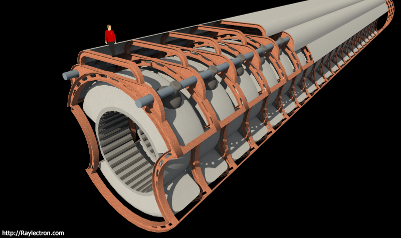
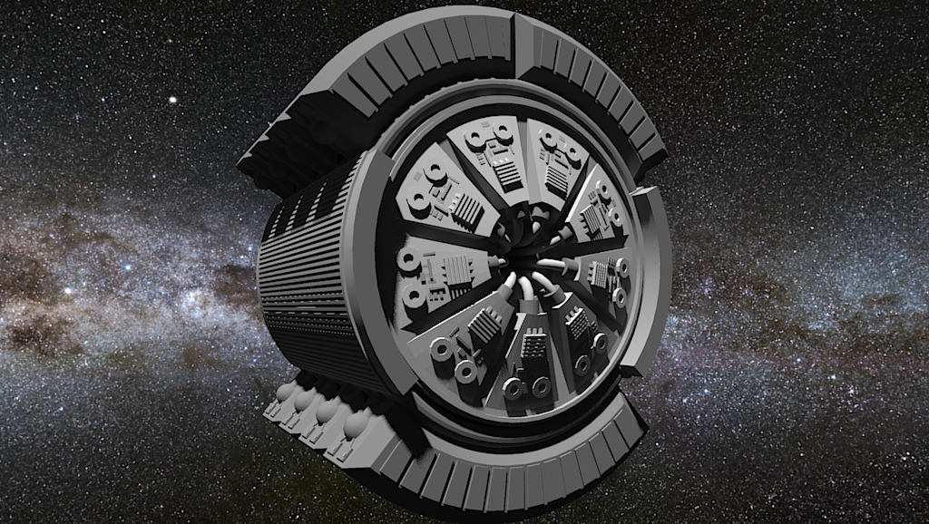
I've been struggling with coming up with a design that works, but I think I'm there now:
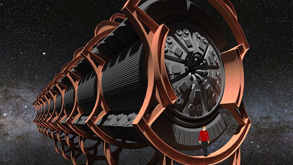
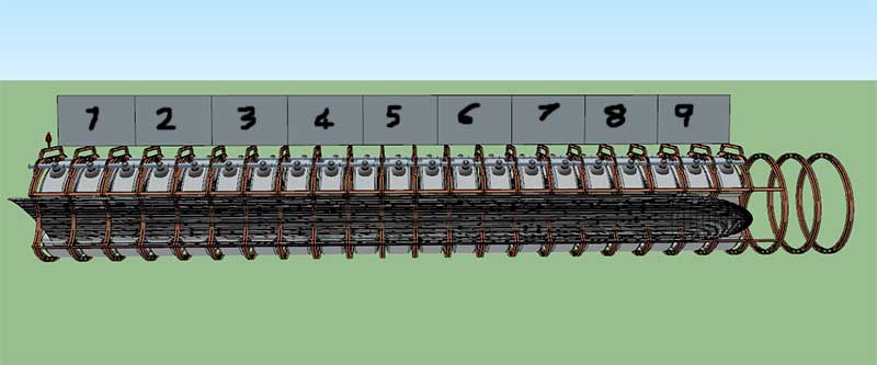
9 "Warp System Engines" per nacelle as per the below, with 9 segments on each.

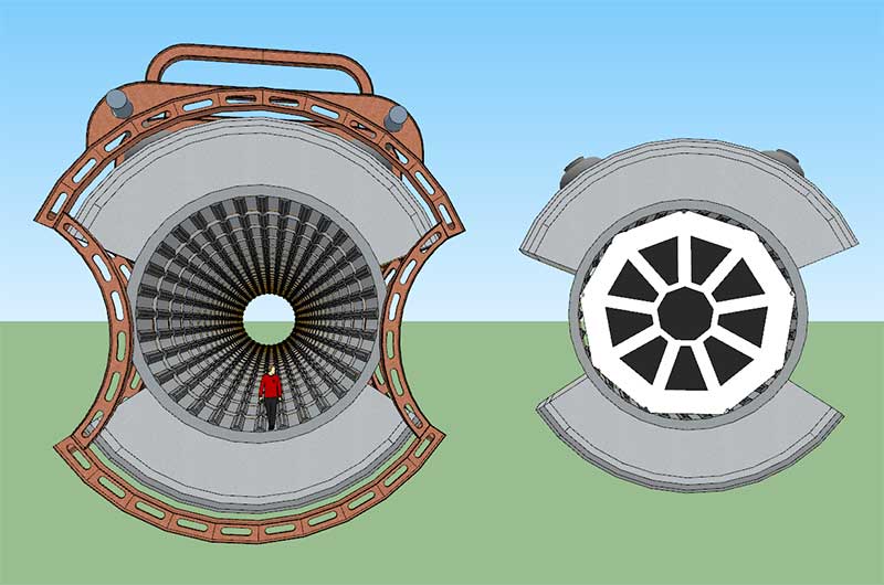
Here's a shot of a single engine. Just need to build some plasma injectors now, and add some infrastructure for data cabling and coolant.
9 "Warp System Engines" per nacelle as per the below, with 9 segments on each.
Here's a shot of a single engine. Just need to build some plasma injectors now, and add some infrastructure for data cabling and coolant.
I've been struggling with coming up with a design that works, but I think I'm there now:
9 "Warp System Engines" per nacelle as per the below, with 9 segments on each.
Here's a shot of a single engine. Just need to build some plasma injectors now, and add some infrastructure for data cabling and coolant.
I absolutely love this. Fits the Engineering display and looks like a chunky precursor to what we saw in TNG.
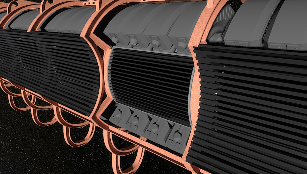
Did a bit more work on the nacelle today, mostly fiddling with the side grilles. I realised that just putting a grille on there wasn't good enough, because not only does it need to vent plasma exhaust into space, it also needs to be airtight or the whole nacelle becomes vacuum. This is what I came up with, a kind of cowling or duct that fits snugly over the engine exhaust. I also had to re-plan where I was putting my pipes and cabling, because without the cowling/duct in place they'd all be melted every time the engines vent plasma :P
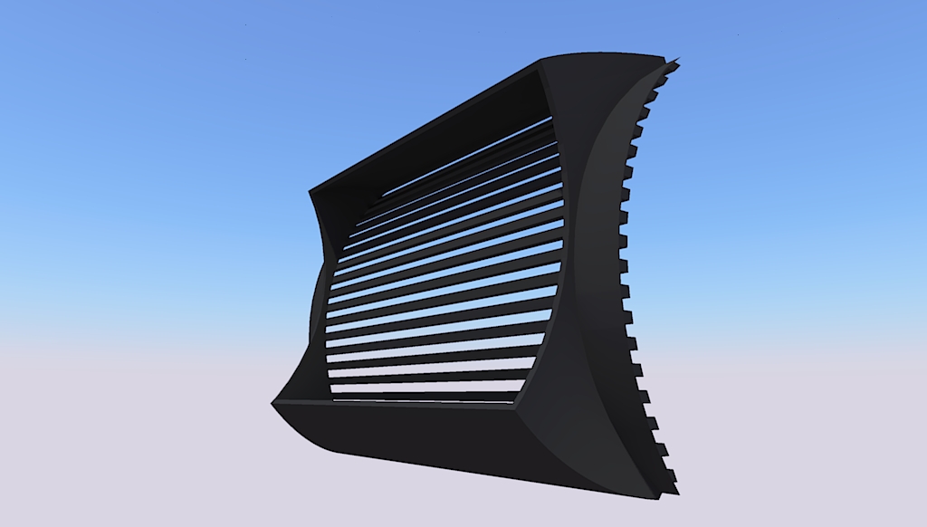
They just bolt right on the side like this:
Not looking forward to making the curved end piece... that's going to be awkward as hell to align with a rectangular exhaust vent.
They just bolt right on the side like this:
Not looking forward to making the curved end piece... that's going to be awkward as hell to align with a rectangular exhaust vent.
Similar threads
- Replies
- 3
- Views
- 316
- Replies
- 482
- Views
- 63K
If you are not already a member then please register an account and join in the discussion!