Good day everyone.
A friend of mine sent me a video from YouTube that showed the original Enterprise under construction in space dock. Done to the TMP score it got me inspired to try my hand at some modeling work as well. With all the talent on display here, I hope to contribute to the discussion as well.
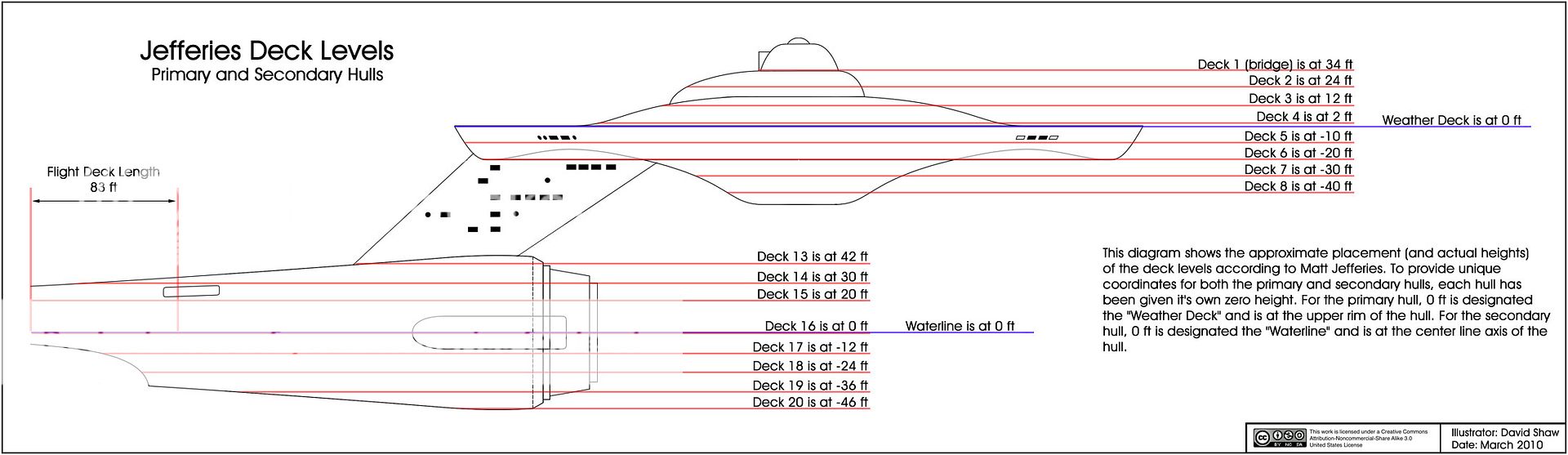
I remember watching the original series on Channel 29, Buffalo NY back in the mid seventies and looked forward to the premiere of the Next Gen as it promised to continue the adventure. With all the different Trek Universes out there, I've found some amazing designs as well as some not so amazing. What I've built up so far is based on the original technical manual and the blueprints that were produced back in 1975 I think. These would be what people are referring to the Franz Joseph Enterprise.
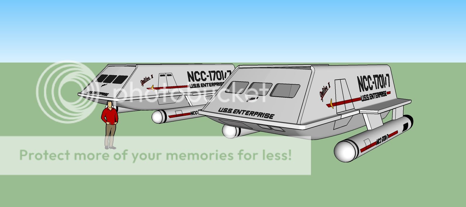
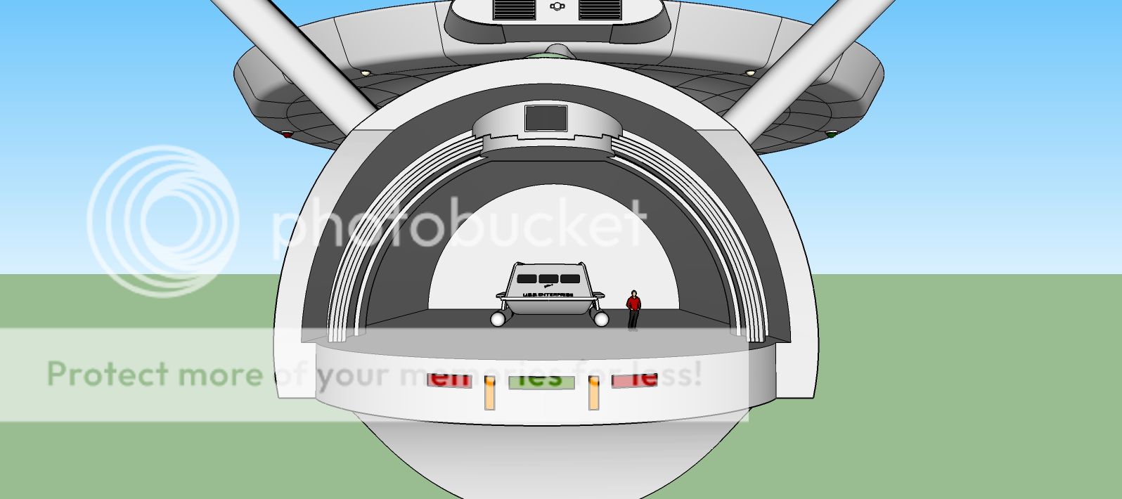
Now I started off with the Galileo Shuttle, so that when I got started on the Enterprise, I had something to reference the scale of the ship. Now here is the shuttle:
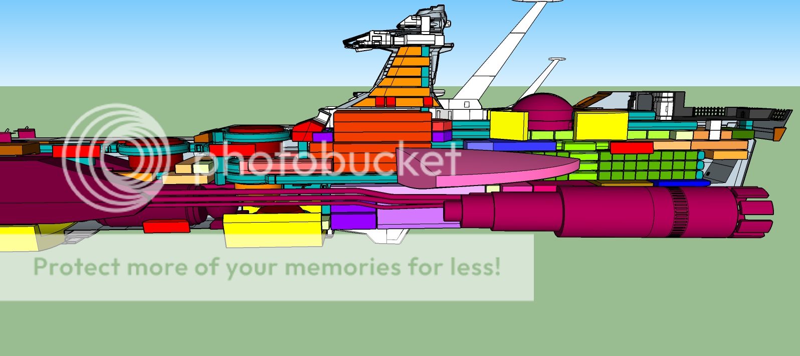
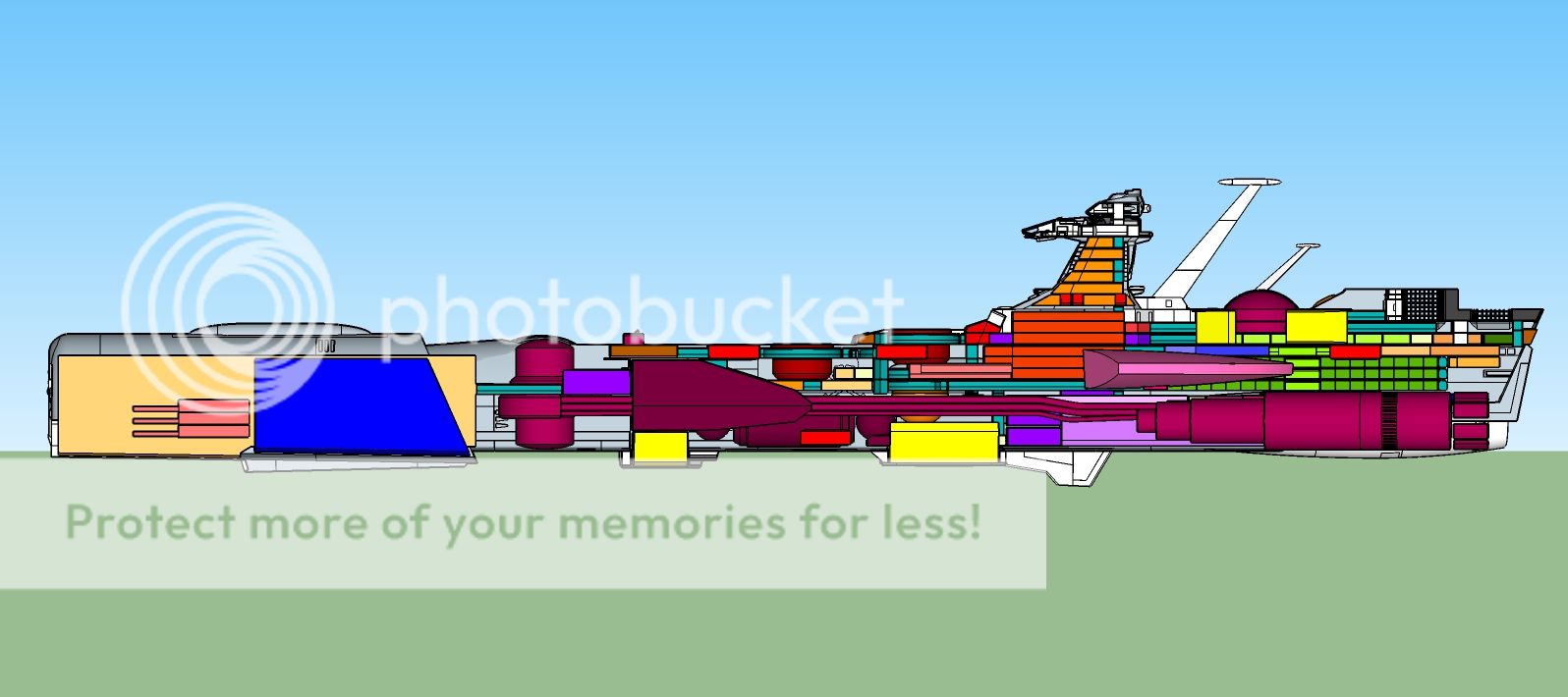
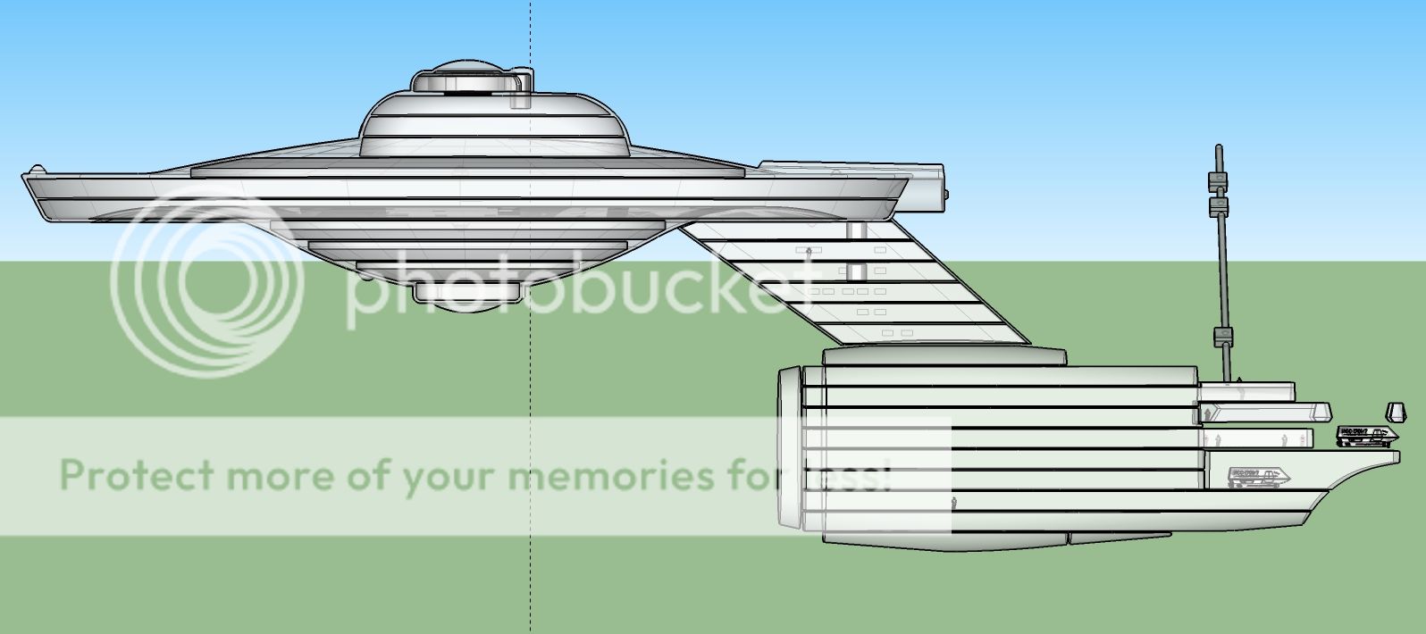
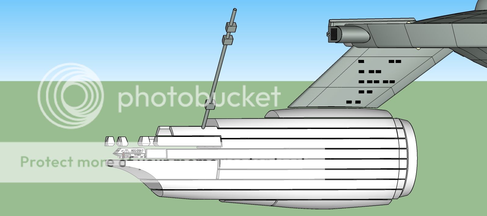
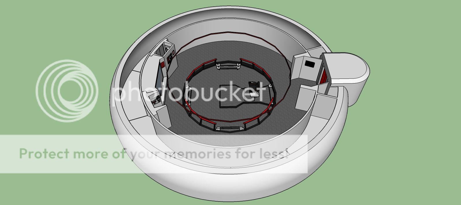
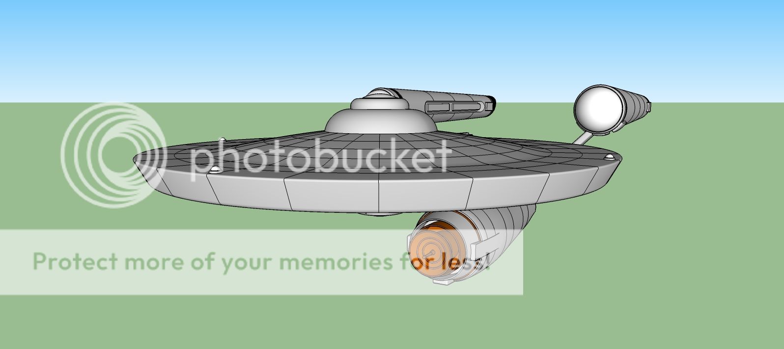
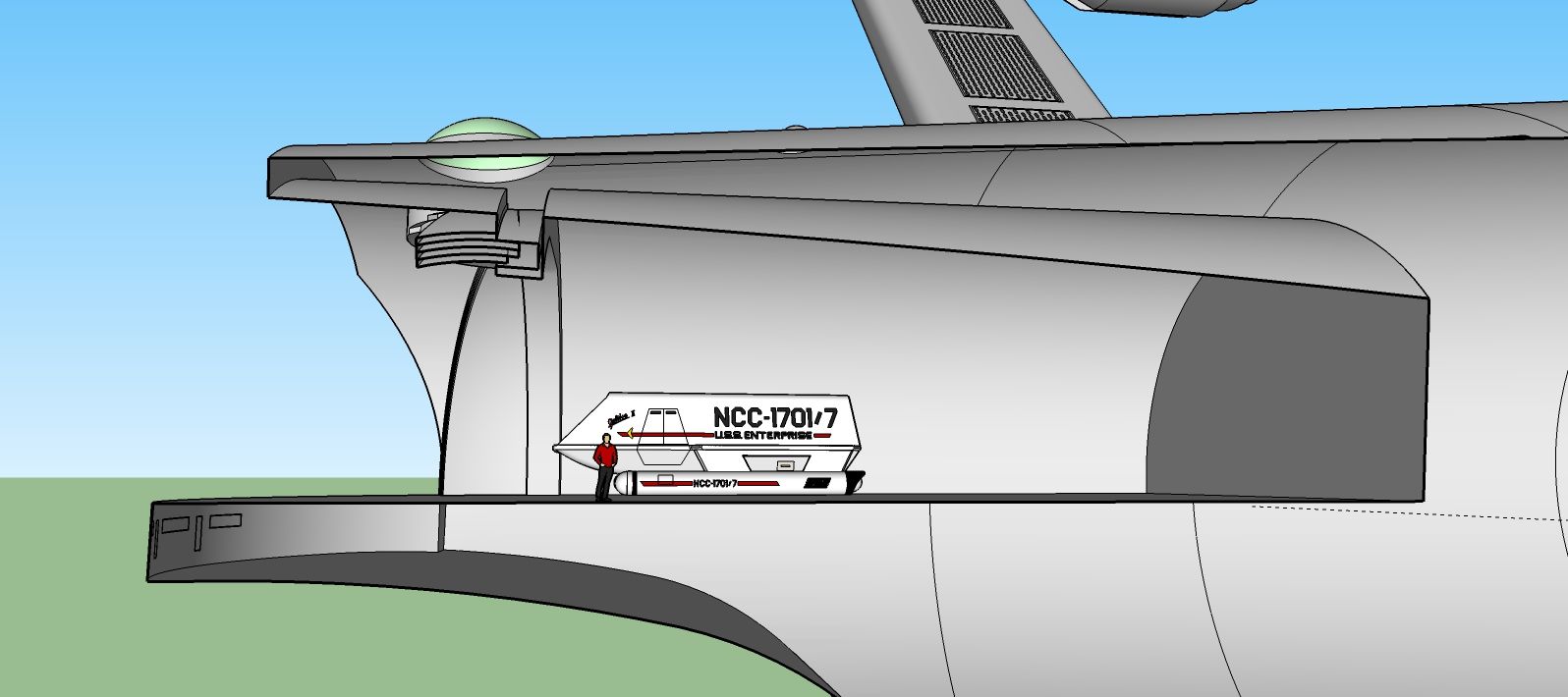
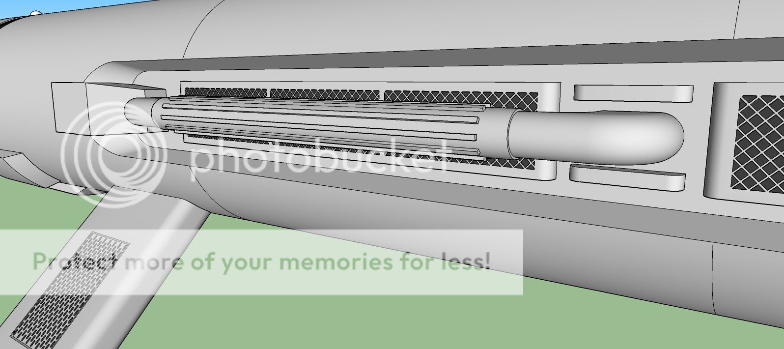
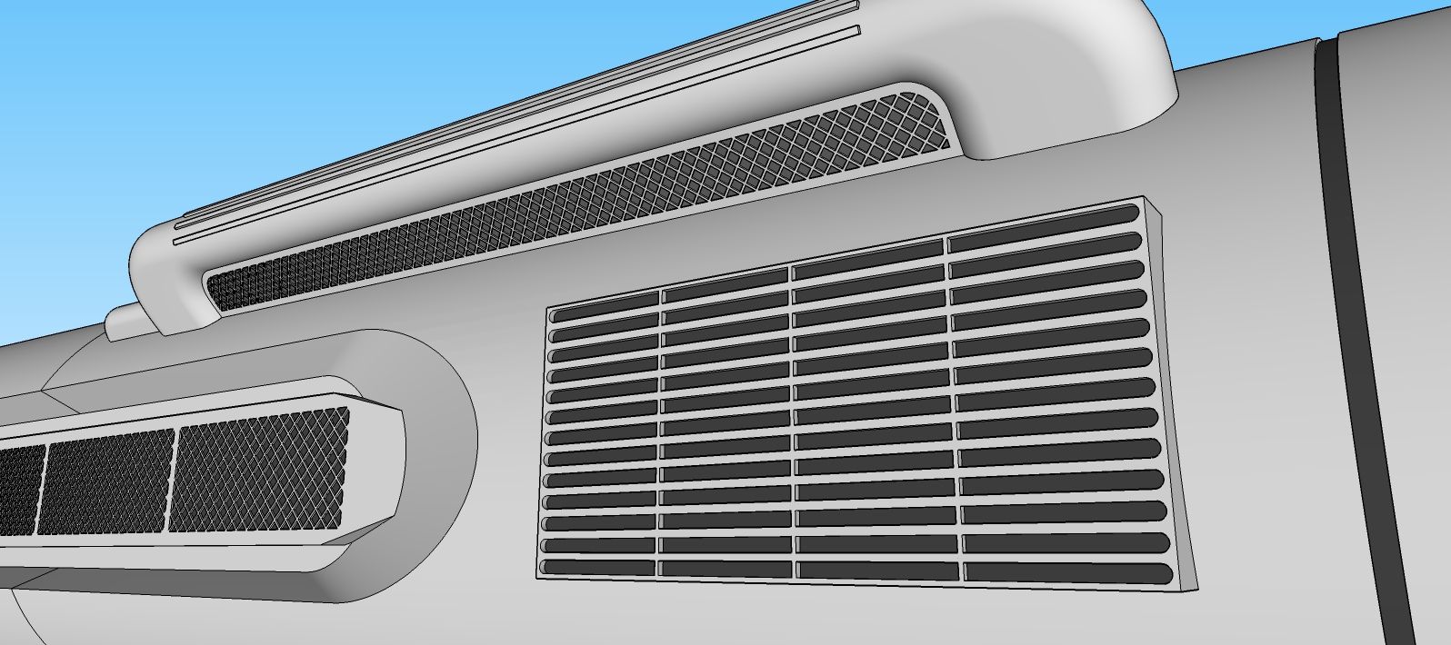
And here is the Enterprise:
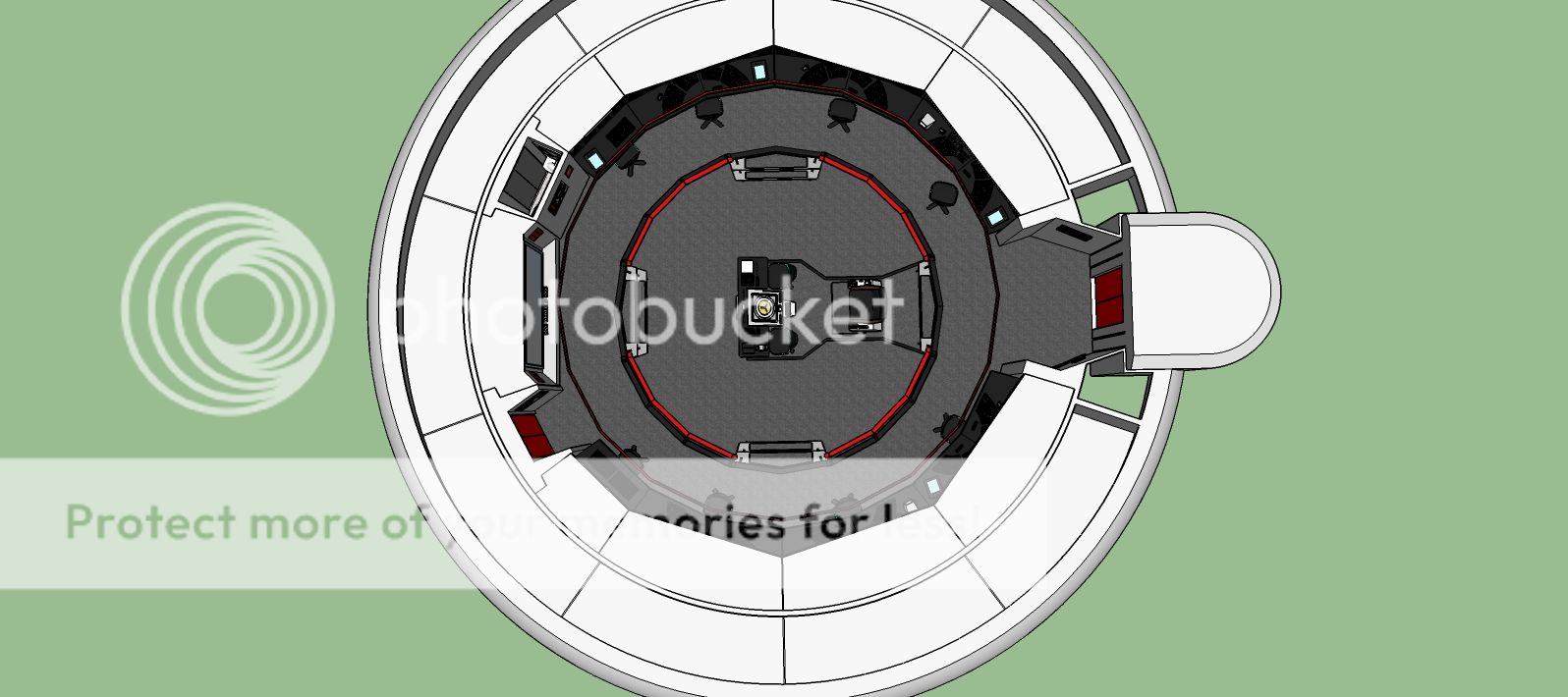
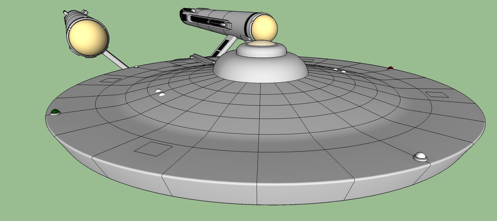
another view:
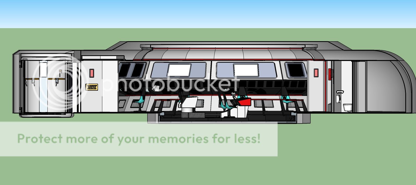
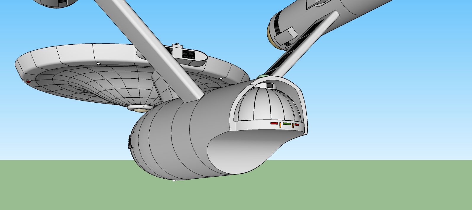
and another:
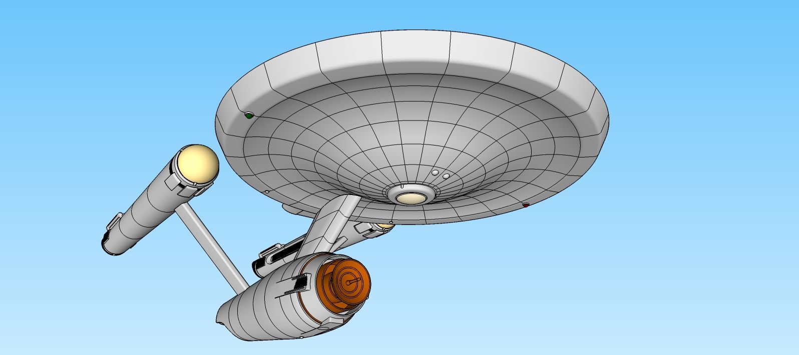
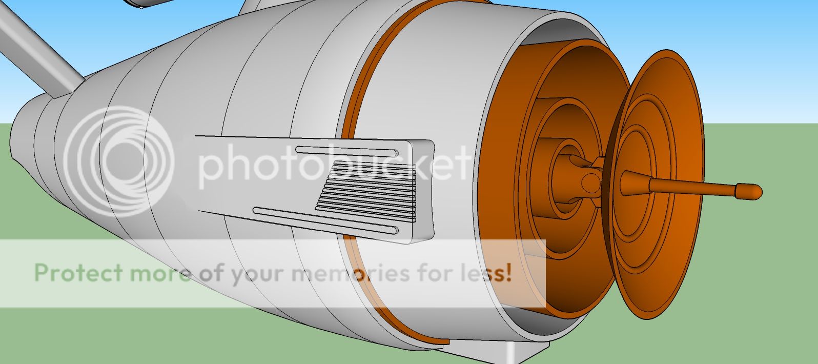
Last one:
My main goal was to create something that matched proportionally to the various plans, blueprints and dimensions that I found. I also used a photo guide to the 11ft. model that is on display at the Smithsonian published by Scott Lowther.
More to come as I build it.
A friend of mine sent me a video from YouTube that showed the original Enterprise under construction in space dock. Done to the TMP score it got me inspired to try my hand at some modeling work as well. With all the talent on display here, I hope to contribute to the discussion as well.
I remember watching the original series on Channel 29, Buffalo NY back in the mid seventies and looked forward to the premiere of the Next Gen as it promised to continue the adventure. With all the different Trek Universes out there, I've found some amazing designs as well as some not so amazing. What I've built up so far is based on the original technical manual and the blueprints that were produced back in 1975 I think. These would be what people are referring to the Franz Joseph Enterprise.
Now I started off with the Galileo Shuttle, so that when I got started on the Enterprise, I had something to reference the scale of the ship. Now here is the shuttle:
And here is the Enterprise:
another view:
and another:
Last one:
My main goal was to create something that matched proportionally to the various plans, blueprints and dimensions that I found. I also used a photo guide to the 11ft. model that is on display at the Smithsonian published by Scott Lowther.
More to come as I build it.


")