-
Welcome! The TrekBBS is the number one place to chat about Star Trek with like-minded fans.
If you are not already a member then please register an account and join in the discussion!
You are using an out of date browser. It may not display this or other websites correctly.
You should upgrade or use an alternative browser.
You should upgrade or use an alternative browser.
Forced perspective, painted backdrops and the refit Enterprise
- Thread starter Mytran
- Start date
Then it's probably more accurate to say:That, I don't know.
Yes?Some of the stages at Paramount have a basement level. Many of the Trek props, costumes and set pieces were stored in these over the years. The warp core probably extended down into this area.
Last edited:
Upon re-examination I believe the TMP intermix "tower" wasn't a "floor" painting but rather some large canvas. When they rolled it out again for TWOK you can notice wrinkles "on" the walls of the level below.
It looks like it was rolled out over a backlit transparency sharing the pulsating plasma energy effect of the upper tower structure (i.e. that part of the canvas was cut out).
Nevertheless, they seemed to have lighting issues and further needed to illuminate the canvas with lights, apparently hidden by the two ladies looking at the impulse engine fuel flow display. You can notice the shadow the physical intermix tower set element casts "towards" Scotty.
Probably some light source at the bottom of the set for the intermix shaft visual effect needed to be hidden, hence this solution?
Bob
Great find on the wrinkles! It does make sense that it could be rolled for easy storage. It might also explain those strange "floorboards" we see in TMP during one scene, since they might well be the actual floor!
I found a picture in my "Making of Phase 2" book that might be interesting:
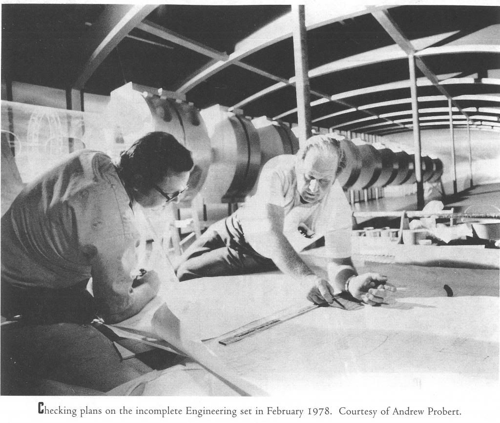
The FP disc segments are clearly seen, diminishing in size as the tube goes on. What's interesting is that the "crystal" segments do not diminish in length (nor are they built beyond a simple connecting rod, since they were never going to be seen on screen.
The backdrop painted is set up and ready, and I do wonder if the idea was ever toyed with of extending the tube even further by included it on the painting. This really would have increased the size and scope of the Engine Room a lot more!
The "real life" length of the horizontal tube can now be estimated more easily, if required - there are 10 FP segments and 3 full size segments - 13 in all, plus the conical junction to the vertical tube.
If each horizontal segment is about 4' in length then the overall length of the tube would be 52'
YMMV, of course")
I found a picture in my "Making of Phase 2" book that might be interesting:
The FP disc segments are clearly seen, diminishing in size as the tube goes on. What's interesting is that the "crystal" segments do not diminish in length (nor are they built beyond a simple connecting rod, since they were never going to be seen on screen.
The backdrop painted is set up and ready, and I do wonder if the idea was ever toyed with of extending the tube even further by included it on the painting. This really would have increased the size and scope of the Engine Room a lot more!
The "real life" length of the horizontal tube can now be estimated more easily, if required - there are 10 FP segments and 3 full size segments - 13 in all, plus the conical junction to the vertical tube.
If each horizontal segment is about 4' in length then the overall length of the tube would be 52'
YMMV, of course
Great picture! But eye-balling the full size segments and assuming Shane Johnson got the reproduction correct (he had been visiting the set) I'd get a length of almost 7' for each H-shaped segment which would put the "real life" pretended overall length of the horizontal shaft at 87' or 26.5 meters (assuming, of course, all elements are supposed to have the same length).
Bob
Upon re-examination I believe the TMP intermix "tower" wasn't a "floor" painting but rather some large canvas. When they rolled it out again for TWOK you can notice wrinkles "on" the walls of the level below.
It's interesting that the shot still works for the FP bottom given that it is at a slightly different angle as shown in TMP.
That's neat.
If each horizontal segment is about 4' in length then the overall length of the tube would be 52'
YMMV, of course
That doesn't take into account the thickness of the rings, right?
Maurice - Yep, I had brain cramp and forgot about the thickness of the discs, oops!
Looking at the picture again (which I didn't do during my hurried earlier entry) I would have to agree with Robert_Comsol - on this ocassion, Shane Johnson may have got it right!
1' for each disc
5' for each transluscent section
So each complete "segment" is 7'
Total length (not including the connecting cone) is 87'
From the cente of the vertical conduit to the start of the first full segment is approx 4' (based on the length of the transluscent section & checked against Shane Johnson)
Now, if the engine room (on a 1,000' TMP-E) is in its official location centred on the Impulse Deflection Crystal, then the horizontal tube at the V-split would not quite reach the pylons (40'-80' short, depending on where the conduit enters the pylons).
This problem could be negated if the "real life" distance between the discs is larger on the FP segments along the horizontal length, around 11'-15' for each complete segment. However, the presence of a crewmen at the far end makes this unlikely - he just doesn't seem that far away!
Maybe they should have used the backdrop painting after all?
Last edited:
Wow, that's one spectacularly bad job of linking.This problem could be negated if the "real life" distance between the discs is larger on the FP segments along the horizontal length, around 11'-15' for each complete segment. However, the presence of a crewmen at the far end makes this unlikely - he just doesn't seem that far away!
Quote your own message and look what you did. hee hee
You could treat the short length as connecting not directly to the warp nacelles but to the energizers and the energizers extend horizontally (but not visible because they are above deck) to the stern and that connects to the nacelles.
Or, you could extend the horizontal segment that is beyond the last disk and consider it long enough to make the diagonal conduits reach the warp pylons. Remember the vertical segment at the bottom of the vertical conduit was extra long as well.
Or, you could extend the horizontal segment that is beyond the last disk and consider it long enough to make the diagonal conduits reach the warp pylons. Remember the vertical segment at the bottom of the vertical conduit was extra long as well.
Or, you could relocate the main engine room level one deck below (I doubt that the upper level could possibly fit in the forward bow) and simply extend the length of the Y-split tubes before they reach the warp nacelles.
On the original set these were quite asymetrical. Theoretically these y-split extensions could also be power lines for the aft phaser port and starboard. I don't think it makes a lot of functional sense to have that much empty space extending on the FP painting beyond the Y-split.
Bob
On the original set these were quite asymetrical. Theoretically these y-split extensions could also be power lines for the aft phaser port and starboard. I don't think it makes a lot of functional sense to have that much empty space extending on the FP painting beyond the Y-split.
Bob
Huh, all this time I somehow thought the horizontal intermix chamber was actually too long to fit, not too short.
If you wanted to pass the studio set as both the impulse engine room (in the saucer) and the warp engine room, you could only fit the engine room set as impulse engine room into the saucer believing that the forced perspective / actual set is the real thing "in-universe", too.
Otherwise the "pretended" length of the horizontal tubes would not fit into the saucer, indeed.
Bob
Otherwise the "pretended" length of the horizontal tubes would not fit into the saucer, indeed.
Bob
Agreed, if adopting the set for the saucer section (although you would need some very short crewmen assigned to Impulse Engineering!)
However, as far as placing the Engine Room in the secondary hull, we have more space to play with - and indeed need to fill! The large cavern aft of the Y-split is an oddity - is there really nothing that Starfleet Engineers could think of to do with the space?
However, as far as placing the Engine Room in the secondary hull, we have more space to play with - and indeed need to fill! The large cavern aft of the Y-split is an oddity - is there really nothing that Starfleet Engineers could think of to do with the space?
However, as far as placing the Engine Room in the secondary hull, we have more space to play with - and indeed need to fill! The large cavern aft of the Y-split is an oddity - is there really nothing that Starfleet Engineers could think of to do with the space?
LOL, apparently not.
^^^ Looking at that screencap gives me an idea.
It seems that curved ceiling over the conduit is intended to match the curve of the top of secondary hull (where engineering is located).
But it appears to me that curvature wouldn't expand out to match the diameter of the secondary hull where the cargo deck/shuttle hangar is located a few decks just below engineering.
Maybe someone better than me with geometry and photo skills could measure the degrees of curve seen in the photo and calculate the size of the secondary hull based on this screencap evidence.
@ Mytran & blssdwlf
Maybe I got an idea: it's a wall of transparent aluminum and the space behind is filled with liquid deuterium?
That was probably the idea, but we'd still have to accomodate the space for the upper level of the engine room and the large bulkhead door that came from above in TWOK.
I'm working on several cross-section views of the engineering hull with the studio sets within. My preliminary work shows that to match the curvature of the outer hull the engine room would have to be located just above the ceiling of the cargo deck
I think we'd arrive at an overall length of less than 1,000 feet.
Bob
Maybe I got an idea: it's a wall of transparent aluminum and the space behind is filled with liquid deuterium?
It seems that curved ceiling over the conduit is intended to match the curve of the top of secondary hull (where engineering is located).
That was probably the idea, but we'd still have to accomodate the space for the upper level of the engine room and the large bulkhead door that came from above in TWOK.
But it appears to me that curvature wouldn't expand out to match the diameter of the secondary hull where the cargo deck/shuttle hangar is located a few decks just below engineering.
I'm working on several cross-section views of the engineering hull with the studio sets within. My preliminary work shows that to match the curvature of the outer hull the engine room would have to be located just above the ceiling of the cargo deck
Maybe someone better than me with geometry and photo skills could measure the degrees of curve seen in the photo and calculate the size of the secondary hull based on this screencap evidence.
I think we'd arrive at an overall length of less than 1,000 feet.
Bob
Similar threads
- Replies
- 18
- Views
- 1K
- Replies
- 192
- Views
- 28K
- Replies
- 482
- Views
- 59K
If you are not already a member then please register an account and join in the discussion!