Wow Donny! Some frikken awesome work here! Wish i'd visited TrekBBS a little more often so i could of seen this sooner!
-
Welcome! The TrekBBS is the number one place to chat about Star Trek with like-minded fans.
If you are not already a member then please register an account and join in the discussion!
You are using an out of date browser. It may not display this or other websites correctly.
You should upgrade or use an alternative browser.
You should upgrade or use an alternative browser.
Donny's TOS Enterprise Interiors
- Thread starter Donny
- Start date
FJ purists such as myself like to think they’re the internal impulse engine housings up in the primary hull.Their function hasn't ever been confirmed on screen, nor is it even certain that the length depicted by the forced perspective prop is even how it would be in-universe.
Some speculate that the tubes sit under the pylons and are connected directly to the nacelles. Others that they are part of the energy conversion/generation systems for primary systems like weapons or deflectors.
It is likely that they are part of the warp engine systems in some manner, as pushing them too hard in The Paradise Syndrome causes the whole area to "burn out".
This is also the episode that as Scotty refers to them as his "wee bairns"


The images look great but none of the videos are showing up on my end. Anyone else have that?
In my headcanon the pipes are a power conversion system. There's several units like this throughout the ship, including the Engine Rooms behind the Impulse EnginesFJ purists such as myself like to think they’re the internal impulse engine housings up in the primary hull.
This is my thought as well, which is convenient because my eventual “Season 1” engine room will be the “impulse deck” in the primary hull and will of course feature these same units. Besides, it makes more sense that the machinery in the middle of the floor in the S2/3 engine room is the more warp-power specific part of the equation, since the active dilithium crystals are housed in this machine.In my headcanon the pipes are a power conversion system. There's several units like this throughout the ship, including the Engine Rooms behind the Impulse Engines
Last edited:
Nah, I don’t think that was ever inferred. As a matter of fact, we don’t even know exactly where in the secondary hull the engine room resides. All of that is up to interpretation.
If you made the Engineering ceiling arch a complete circle how different would it be from the circumference of the Secondary Hull?
Not only the power center behind the mesh grid, but that entire engineering set is quite distorted. The dilithium housing in the middle of the floor was much bigger than we thought, while the ladders and height of the upper level were shorter. It seems to have been built with a distorted foreshortening to accomodate certain lenses which were used to create the impression of a much larger space.
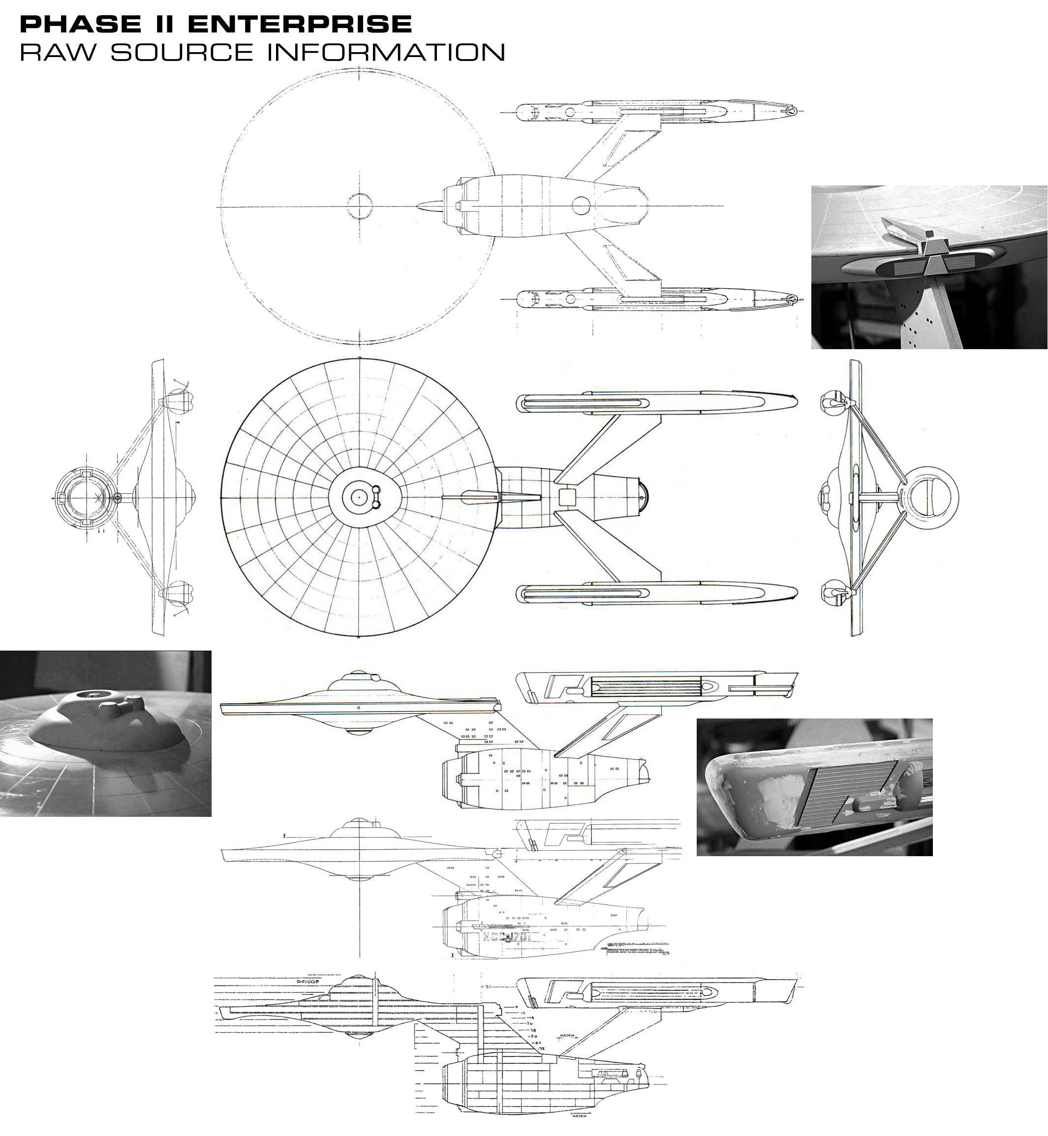
If one were to measure the considerable diameter of the secondary hull just forward of the pylons, where Jefferies shows engineering to be located on his Phase II cross section, they might gain an impression of just how big that engineering space was intended to be. Not only that but, they might also gain insight into how a full size flight deck might have been built, since that would have been just aft of the engineering location.
If one were to measure the considerable diameter of the secondary hull just forward of the pylons, where Jefferies shows engineering to be located on his Phase II cross section, they might gain an impression of just how big that engineering space was intended to be. Not only that but, they might also gain insight into how a full size flight deck might have been built, since that would have been just aft of the engineering location.
So you can treat the engineering space the same as the shuttle deck: impressionistically, not literally. Although Donny of course has been wonderfully literal.
If the flight deck is "just" aft of engineering, then where do those tubes go?
I don't entirely buy all of this https://vignette.wikia.nocookie.net...ision/latest?cb=20110625031327&path-prefix=en but it does try to figure out a relationship between engineering and the shuttle.
(Interesting - the Memory Alpha page says that he did a first draft based on Franz Joseph.)
Not “just” aft. Presumably those tubes fill the space under the pylons.
It is worth remembering that the maquette of the flight deck was also distorted, and that the draft Jefferies did that ended up in TMoST was of that maquette- maybe a construction guide for Datin. In other words, not meant to reflect the deck or the way it fit in the ship, but rather the distorted model.
It is worth remembering that the maquette of the flight deck was also distorted, and that the draft Jefferies did that ended up in TMoST was of that maquette- maybe a construction guide for Datin. In other words, not meant to reflect the deck or the way it fit in the ship, but rather the distorted model.
I personally like the idea that Main Engineering is in roughly the same spot it is on the Refit, with power conduits stretching back just inside the inner spine of the secondary hull towards the nacelle pylons. This allows space for a cargo bay immediately forward of the hangar deck as well, which I thought has always made logical sense. Best to keep the cargo near one of the points in which cargo is brought on board.
Strategic Designs follows this depiction, and also has a 4-deck vertical warp core, so-to-speak, underneath the Dilithium Reactor Chamber in the middle of the floor in Main Engineering. I've actually been itching to bring that depiction to life in 3D.
You can see the Strategic Designs cutaway here: http://www.cygnus-x1.net/links/lcar...nx-1700/sd-constitution-nx-1700-sheet-7-X.jpg and here: http://www.cygnus-x1.net/links/lcar...nx-1700/sd-constitution-nx-1700-sheet-8-X.jpg (note the cross section of engineering on the second page)
Last edited:
It looks like that would be at odds with episodes that show or follow the corridor on stage 9 that goes straight into main engineering all the way down from its opposite end, like "Journey to Babel" does, shown below, because that corridor would be inside the main deflector area, if not in fact outside the front of the ship. But myself, I wouldn't consider it to be an actual "problem," because no arrangement is going to be perfectly satisfactory. IIRC, a similar problem of an impossible corridor near main engineering and going out the front of the secondary hull occurs in TMP.I personally like the idea that Main Engineering is in roughly the same spot it is on the Refit, with power conduits stretching back just inside the inner spine of the secondary hull towards the nacelle pylons. This allows space for a cargo bay immediately forward of the hangar deck as well, which I thought has always made logical sense. Best to keep the cargo near one of the points in which cargo is brought on board.
Strategic Designs follows this depiction, and also has a 4-deck vertical warp core, so-to-speak, underneath the Dilithium Reactor Chamber in the middle of the floor in Main Engineering. I've actually been itching to bring that depiction to life in 3D.
You can see the Strategic Designs cutaway here: http://www.cygnus-x1.net/links/lcar...nx-1700/sd-constitution-nx-1700-sheet-7-X.jpg and here: http://www.cygnus-x1.net/links/lcar...nx-1700/sd-constitution-nx-1700-sheet-8-X.jpg (not the cross section of engineering on the second page)
http://tos.trekcore.com/hd/thumbnails.php?album=62&page=6
Jefferies might've intended the engine room for the 1977 refit to be just at the root of the engine pylons as he left a large and tall compartment there with a hatch indicated on ship's back above it, possibly to access the vertical engine core. That'd be aft of where the movie refit room ended up. @Shaw did some comparison's of Jefferies' TOS and refit cutaways to see how much commonality there was. I can't seem to find it here on the BBS though.
Speaking of those cutaways, the Phase II one can be seen on this...
Speaking of those cutaways, the Phase II one can be seen on this...
Last edited:
@Maurice Is this the post you are looking for?@Shaw did some comparison's of Jefferies' TOS and refit cutaways to see how much commonality there was. I can't seem to find it here on the BBS though.
Speaking of those cutaways, the Phase II one can be seen on this...
https://www.trekbbs.com/threads/another-fan-attempt-at-tos-deck-plans.45261/#post-1331214
I personally like the idea that Main Engineering is in roughly the same spot it is on the Refit, with power conduits stretching back just inside the inner spine of the secondary hull towards the nacelle pylons. This allows space for a cargo bay immediately forward of the hangar deck as well, which I thought has always made logical sense. Best to keep the cargo near one of the points in which cargo is brought on board.
I have come around to this view as well. Using strictly TOS (and maybe a few TAS) design elements, one could repeat the Probert TMP layout within Jefferies’ general cross section layout, and not be too far off from what Jefferies hints is going on.
The diameter of the secondary hull is considerably greater where engineering would be, however. So the caveat I see is an engineering space at the dorsal housing a vertical shaft AND a connection to a horizontal shaft running aftwards towards an engineering room just forward of the pylons. The cargo space would be roughly UNDER this aft engineering space, linked to the flight deck.
Last edited:
As far as the power systems go, I found this discussion to be quite enlightening:
https://www.trekbbs.com/threads/antimatter-converter-assembly.293558/
For those who haven't read it yet, you should check it out.
https://www.trekbbs.com/threads/antimatter-converter-assembly.293558/
For those who haven't read it yet, you should check it out.
We're only talking about a portion of the hull to fit the curved contour of the ceiling struts visible on the set though. I've long been aware that the ladders and upper levels were far from a close match (anywhere from 2 to 5 feet too short!) but I've never thought to combine that with the forced perspective tubular machinery. before. All in all, it could be suggestive of a truly massive Engine Room!Not only the power center behind the mesh grid, but that entire engineering set is quite distorted. The dilithium housing in the middle of the floor was much bigger than we thought, while the ladders and height of the upper level were shorter. It seems to have been built with a distorted foreshortening to accomodate certain lenses which were used to create the impression of a much larger space.
...
If one were to measure the considerable diameter of the secondary hull just forward of the pylons, where Jefferies shows engineering to be located on his Phase II cross section, they might gain an impression of just how big that engineering space was intended to be. Not only that but, they might also gain insight into how a full size flight deck might have been built, since that would have been just aft of the engineering location.

Jefferies' sketch was certainly drawn as a forced perspective set, but when Datin came to built the miniature he doesn't seem to have followed it to that extent, as the observation corridor and booths are built on the same, horizontal level. It is true that the overall set is slightly conical, but that seems to have been done to match the aft end of the Engineering Hull.It is worth remembering that the maquette of the flight deck was also distorted, and that the draft Jefferies did that ended up in TMoST was of that maquette- maybe a construction guide for Datin. In other words, not meant to reflect the deck or the way it fit in the ship, but rather the distorted model.
Yes, somewhere there is an interview with Datin where he says he didn’t follow Jefferies’ plans exactly.
Yes, that's the thread.@Maurice Is this the post you are looking for?
https://www.trekbbs.com/threads/another-fan-attempt-at-tos-deck-plans.45261/#post-1331214
Donny, is there a direct link to those videos? They don't show up for me, for some reason.
Similar threads
- Replies
- 482
- Views
- 58K
- Replies
- 43
- Views
- 11K
If you are not already a member then please register an account and join in the discussion!