While making progress on the warp engines I'm starting to get a better understanding of how they were constructed for the model.
-
Welcome! The TrekBBS is the number one place to chat about Star Trek with like-minded fans.
If you are not already a member then please register an account and join in the discussion!
You are using an out of date browser. It may not display this or other websites correctly.
You should upgrade or use an alternative browser.
You should upgrade or use an alternative browser.
Another fan attempt at TOS deck plans
- Thread starter Shaw
- Start date
- Status
- Not open for further replies.
Not to be a stick in the mud, but are you sure the secondary hull is that conical? I though it had a little more pudge around the middle?
If you were going to build this model, you would start by using that curve on a lathe. After that you create the indentations (the ones on either side and one on the bottom), which changes the way the curve looks when seen from the top, bottom or sides.
What is displayed in that image is the perfect curve of the secondary hull, the one that is hardest to find from normal views in most plans, but most important for actually building the model.
More importantly, that curve has been cross checked against the actual model with tons of different images... mostly of the side that has no indentation spoiling the actual curve. When the indentation is added, it matches what most people are expecting to see in plans (a slightly greater shallowing of the curve towards the front).
Also, any time my studies diverge from Casimiro, Kerr, Sasser or Sinclair, I triple check my work to see why I got a different result. That was what I was doing between August of 2008 (when I released my primary hull study) and January of 2009 (when I finalized that curve).
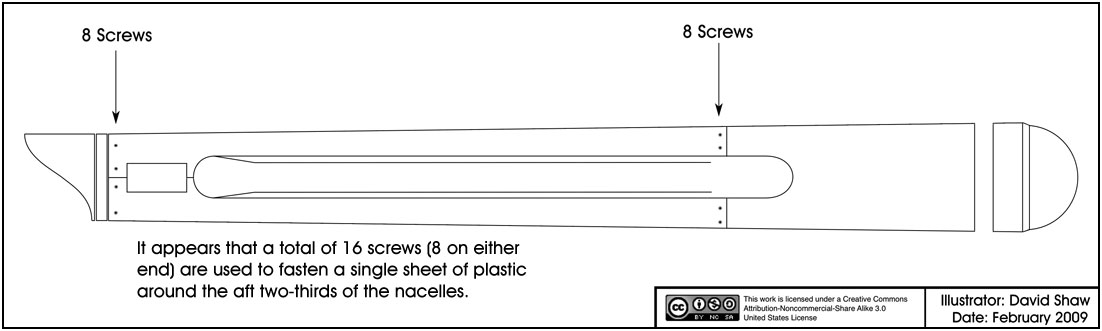
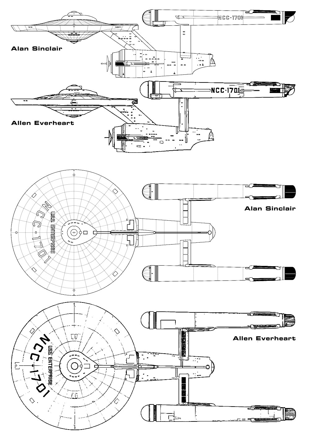
Right now my studies of the nacelles are stalled right where you see them because I am attempting to accurately document the precise locations of each of the 16 screws on each nacelle. The screw locations shown above are generalized, their actual placement is not a perfect pattern and not the same for both nacelles (meaning 32 unique locations). Complicating this is the fact that originally they were puttied over, making them hard to make out... specially around the middle body area (though Casimiro does note the aft ones on his plans). Strangely enough, the first person to note the existence of those middle screws was Allen Everhart in his plans of the model from the 1980s (as seen in this comparison with Sinclair's)
Additionally, these plans are going to need to be altered when done to be used as plans for the ship... I'm doing the model right now. And the model isn't symmetric.
But don't worry about asking... people asked the exact same thing when I finalized the same curve on the 33 inch model, which changed in the final plans when the indentations were added (and why I include an unspoiled version of the curve with those plans for people wanting to actually build the model).
What is displayed in that image is the perfect curve of the secondary hull, the one that is hardest to find from normal views in most plans, but most important for actually building the model.
More importantly, that curve has been cross checked against the actual model with tons of different images... mostly of the side that has no indentation spoiling the actual curve. When the indentation is added, it matches what most people are expecting to see in plans (a slightly greater shallowing of the curve towards the front).
Also, any time my studies diverge from Casimiro, Kerr, Sasser or Sinclair, I triple check my work to see why I got a different result. That was what I was doing between August of 2008 (when I released my primary hull study) and January of 2009 (when I finalized that curve).
Right now my studies of the nacelles are stalled right where you see them because I am attempting to accurately document the precise locations of each of the 16 screws on each nacelle. The screw locations shown above are generalized, their actual placement is not a perfect pattern and not the same for both nacelles (meaning 32 unique locations). Complicating this is the fact that originally they were puttied over, making them hard to make out... specially around the middle body area (though Casimiro does note the aft ones on his plans). Strangely enough, the first person to note the existence of those middle screws was Allen Everhart in his plans of the model from the 1980s (as seen in this comparison with Sinclair's)
Additionally, these plans are going to need to be altered when done to be used as plans for the ship... I'm doing the model right now. And the model isn't symmetric.
But don't worry about asking... people asked the exact same thing when I finalized the same curve on the 33 inch model, which changed in the final plans when the indentations were added (and why I include an unspoiled version of the curve with those plans for people wanting to actually build the model).
Not to be a stick in the mud, but are you sure the secondary hull is that conical? I though it had a little more pudge around the middle?
This is very prelim I'm sure and Shaw will get it right as he always seems to do.
I do agree that there is some tweaking to do. The "fattest" point in the secondary hull is just aft of that front bevel.
http://www.cloudster.com/Sets&Vehicles/STEnterprise/ent63.jpg
The cut-through gives a good idea as to the actual shape. Hope this helps, Shaw.
This one is a better shot, and this one is pretty nice too... I have all of those images and a few hundred more that I've been working from for almost a year now.do agree that there is some tweaking to do. The "fattest" point in the secondary hull is just aft of that front bevel.
http://www.cloudster.com/Sets&Vehicles/STEnterprise/ent63.jpg
The cut-through gives a good idea as to the actual shape. Hope this helps, Shaw.
It is important to recall that originally the windows where just painted on, so surface shapes around were windows were added are given less weight than similar areas that hadn't been violated by later revisions (same was applied in the primary hull curves).
Shaw, as someone who's tried to build the engineering hull a hundred times (and failed, or scrapped the file before finishing it the first time) and as an amateur draftsman, I understand what I'm seeing. ")
Still, I can't agree with your interpretation of the images. Both of those still show the initial hull profile as curving back towards the center axis, right behind where the forward edge of the neck meets the hull. It's not a huge change (certainly not as apparent as the Phase II and TMP hulls), but it's a bit more severe that what you've shown in your illustrations.
Hell, I'd even suggest that the actual point of change is really a vertical seam between the ends of the boards. The second picture looks like it shows the seams between the boards that make up the hull, and it looks as if one of those faint lines might mark the widest portion of the hull.
I'm not trying to be tosser, I'm just offering another set of eyes.
BTW, good catch on the window problem. The windows on the engineering hull aren't horizontally aligned with the deck structure. They're actually aligned parallel to the surface itself, as if they were applied by keeping the hull on a lathe and rotating it to stencil/cut the windows.
Whoops.
Last edited:
If I may chime in here with an observation for a moment.
In many respects Shaw's project echoes my own because he's trying to reconcile the inconsistencies and depict an integrated realistic ship as opposed to just reproducing a filming model.
Production compromises can inhibit the construction of a replica how it is actually envisioned due to time constraints as well as lack of resources. When I look at the shuttlecraft mockup I see where I'm reasonably certain compromises were made to "get the show in the can" so to speak. In other words they didn't have the time and money for perfection. In those cases, and particularly where the imperfections aren't very clear onscreen, then I err on the side of interpreting it how it was likely or could likely have meant t to have been initially.
Regarding the 11ft. TOS E the most obvious example of this is the unfinished side and unlighted side. To that extent we're left to speculate whether that side is indeed symetrical with the visible completed starboard side or if it was perhaps asymetrical. The only real clue we have is that reverse decals were made (though rarely used I believed) to film the ship in reverse as if we were actually seeing the port side. To me this means the unfinished port side was meant to be pretty much symetrical with the starboard side.
I've studied Franz Joseph's and David Winfrey's drawings of the shuttlecraft and to me it looks as if they barely looked at the original source material. In contrast Shaw and others around here as well are not only painstakingly studying others' drawings but the filming model itself and trying to reproduce exact shapes and proportions. Even MJ's drawings differ from the finished model.
More succinctly I think Shaw is doing a fantastic job here. I simply want to say, though, that interpreting the model is a challenge in itself. Do you accept it as is, or do you perceive it as it was initially intended and depict that. I say this because there's no questions that thinga might have been more precise if the TOS producers had had the budget and resources of a feature film which is what a show of TOS' ambition and vision really called for.
I've studied Franz Joseph's and David Winfrey's drawings of the shuttlecraft and to me it looks as if they barely looked at the original source material. In contrast Shaw and others around here as well are not only painstakingly studying others' drawings but the filming model itself and trying to reproduce exact shapes and proportions. Even MJ's drawings differ from the finished model.
I wouldn't accuse FJ or Winfrey of being lazy or stupid, especially considering that all they had was the drawings published in TMoST, any mail correspondence they could get a hold of or initiate, and the reruns of the show itself, viewed through TVs with varying clarity, color balance, and signal reception...
...and without the benefit of VCR's or screencaps.
Besides, some people simply can't see subtle visual differences, let alone figure out what they are seeing.
Drafting is simply illustrating what object looks like from a given angle onto a flat plane.
Figuring out what you are drawing is a bit more difficult, especially if you can't hold a ruler and calipers to the object itself.
Of course, I've never had anything below a 98% in my CAD or drafting courses, and I was the idiot who picked a crown wheel for his reverse engineering project.
Perhaps I'm not the best example.
 :rolleyes:")
"I'm alright. Don't nobody worry 'bout me."
I'm referring to the area of the hull that's the widest part of the hull, where the neck and the sensor boxes are.
I'm referring to the area of the hull that's the widest part of the hull, where the neck and the sensor boxes are.
Actually, it is funny you brought that up... because that is a perfect case of throwing the baby out with the bath water.BTW, good catch on the window problem. The windows on the engineering hull aren't horizontally aligned with the deck structure. They're actually aligned parallel to the surface itself, as if they were applied by keeping the hull on a lathe and rotating it to stencil/cut the windows.
Casimiro believes that all the windows on the secondary hull are like that (and changed them on his version 2.0 plans), but this is actually incorrect. The three original rows of windows (one row below the pendant and two above) that were originally painted on the model are parallel to each other. The additional windows cut into the model later on to add more detailing match Casimiro's observations on this.
So fans of Casimiro's work should use some of the windows from his 1.0 plans and some from his 2.0 plans for the secondary hull and you'll be in great shape. And maybe he'll have noticed the mistake and corrected it by version 3.0.
As the first version of my plans is going to be of the original pilot configuration, I won't be displaying that detail in them as the problem didn't exist until the series alterations to the model.
I'm certainly not accusing FJ or David Winfrey of being lazy or stupid. I'm just saying that their finished works had little more than passing resemblance to the items they were drawing. And FJ likely had access to more archival material.
But even after I got my first FJ blueprints when they were first released I quickly identified it wasn't what I was seeing onscreen. And yet didn't Mike McMaster draw up amazing blueprints of tha bridge as well as the Klingon Battlecruiser in the same early to mid '70s era?
Down the road I want to draw up my take on the Pike era E and I will try to do much of what Shaw is doing, using stills of the filming model itself to discern exact shapes, sizes, contours and proportions as well as studying the drawings of Alan Sinclair, Charles Casimiro, MJ and additionally those of aridas, CRA and Shaw himself. Indeed I'm doing that already in regards to the shuttlecraft as I'm actually going back to correct some things on sheets I had already completed.
And FJ likely had access to more archival material.
In my discussions with FJ's daughter for my web site, I've heard nothing to convince me that FJ had special access to any behind-the-scenes materials which would have facilitated the creation of or enhanced the accuracy of his work.
And yet didn't Mike McMaster draw up amazing blueprints of tha bridge as well as the Klingon Battlecruiser in the same early to mid '70s era?
Yes, although there are still relatively minor discrepancies in McMaster's work. If memory serves, one example of inaccuracy in the bridge plans is that he has an incorrect number of "warp speed" indicator lights on the helm console. We can only speculate about how McMaster created his drawings, and the references he had, since he died tragically in the 1980s.
^^ Fair enough. And I don't want to come across as slagging someone else's work.
My basic point, though, that I started with a couple of posts back comes down to: trying to exactly replicate a production representation that likely has been compromised in some way due to TV production constraints or trying to reproduce a more "real" vehicle that the filming miniature is supposed to represent, and if the latter then how far do you deviate from the filming miniature and mockups?
A case in point. Somewhere upthread it's mentioned that the scaling of the filming miniature actually comes out to about 944ft. for a real ship. Do you stick with that or just scale up the ship to 947ft. while retaining all the exact shapes, contours and proportions? Or did I misunderstand what I read?
And FJ likely had access to more archival material.
In my discussions with FJ's daughter for my web site, I've heard nothing to convince me that FJ had special access to any behind-the-scenes materials which would have facilitated the creation of or enhanced the accuracy of his work.
And yet we know, from her timeline, that he met with Jefferies and Roddenberry and others to discuss the pilot GR was preparing.
It is hard to imagine these people commenting on Franz Joseph's work, which we know they did, and Franz Joseph not availing himself of their expertise in the least. After all, he was still working on the Technical Manual when he met them, wasn't he?
For whatever it's worth, every since I saw Jeffries floorplan sketch of his Herberium/rec room in the "Star Trek Sketch Book" I've wondered whether FJ had access to this before the rest of us, since his secondary hull "botany section" seems to be based on MJ's sketch? Then again, there's quite a bit of difference as well, so maybe it's just a coincedence? Can FalTorPan, or anyone, shed light on this?
RobertScorpio
Pariah
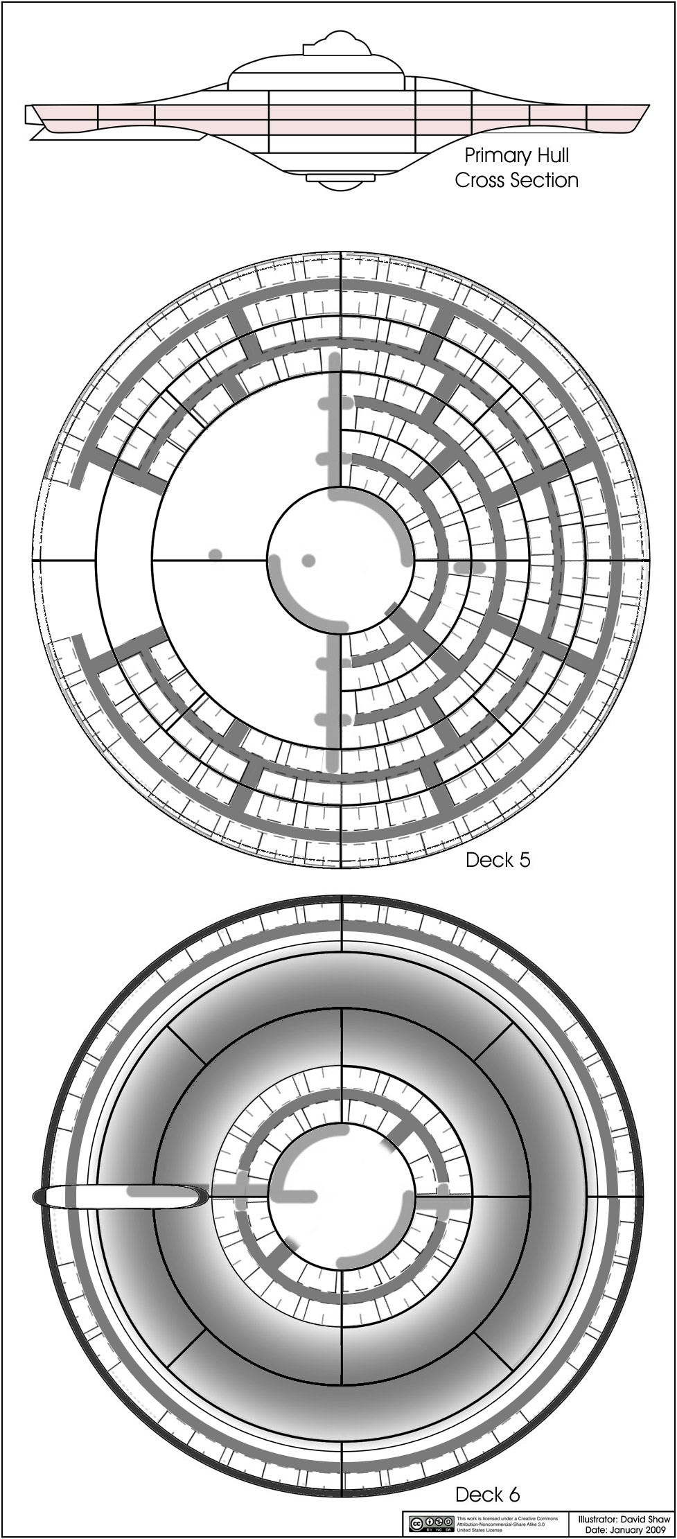
This is my most recent sketch of the cabins on decks 5 and 6...
Even though I haven't sketched out deck 4 yet, the number of cabins in ring 1 of that deck should be similar to the number in ring 1 of deck 6.
Also, you guys might notice that there is a ton of room across the corridor from the cabins in ring 4 on deck 6. That area isn't deep enough for cabins (like what we saw in the show), but there is a lot of room for something else before the deck narrows to a height shorter than normal use.
These are pretty coo..bravo zulu
Rob
I'm rather gratified that Shaw's doing the pilot version of the ship, since the resolution of the bridge question in my plans hinges upon how well the bridge fits under that dome in the pilots.
It'll probably still need some tweaking to fit in a forward facing direction, but I need to know how much tweaking is needed.
It'll probably still need some tweaking to fit in a forward facing direction, but I need to know how much tweaking is needed.
Thanks for the encouragement and input guys!
I (like others) believed that the original US Navy frigates followed Joshua Humphreys designs very closely, and that frigates of the same rate of those original six would be pretty much equivalent to each other. While discussing this subject with aridas I was informed that the builders of the Constellation had modified the design and made her faster than her sister ships.
The ideal designs that Jefferies made aren't fully reflected in the models. And considering that the Enterprise is actually four large pieces connected by supports, it shouldn't be surprising to find that those pieces aren't in their originally intended positions relative to each other. Beyond the overall length issue, there is the fact that both models have their nacelles closer together than Jefferies had specified.
But we are really talking about half an inch in difference on the actual model. Move the nacelles back that half an inch and you'll get the 947 foot length.
Where did that half an inch go?
Most likely it was a compromise needed for the construction... and there were lots of compromises made. Remember, the model was late (which is why the 33 inch model was used for most of the effects), but they needed the big model for the most important effects shot in The Cage, the zoom-in on the bridge (which was to sell the size of the Enterprise to the audience).
One of those interesting things about the construction of the 11 foot model is that the starboard nacelle doesn't have the trench on it's inboard side like the port nacelle. During the series the trench was actually painted on, but when the Smithsonian got the model they painted over that detail (among others) before putting the model on display.
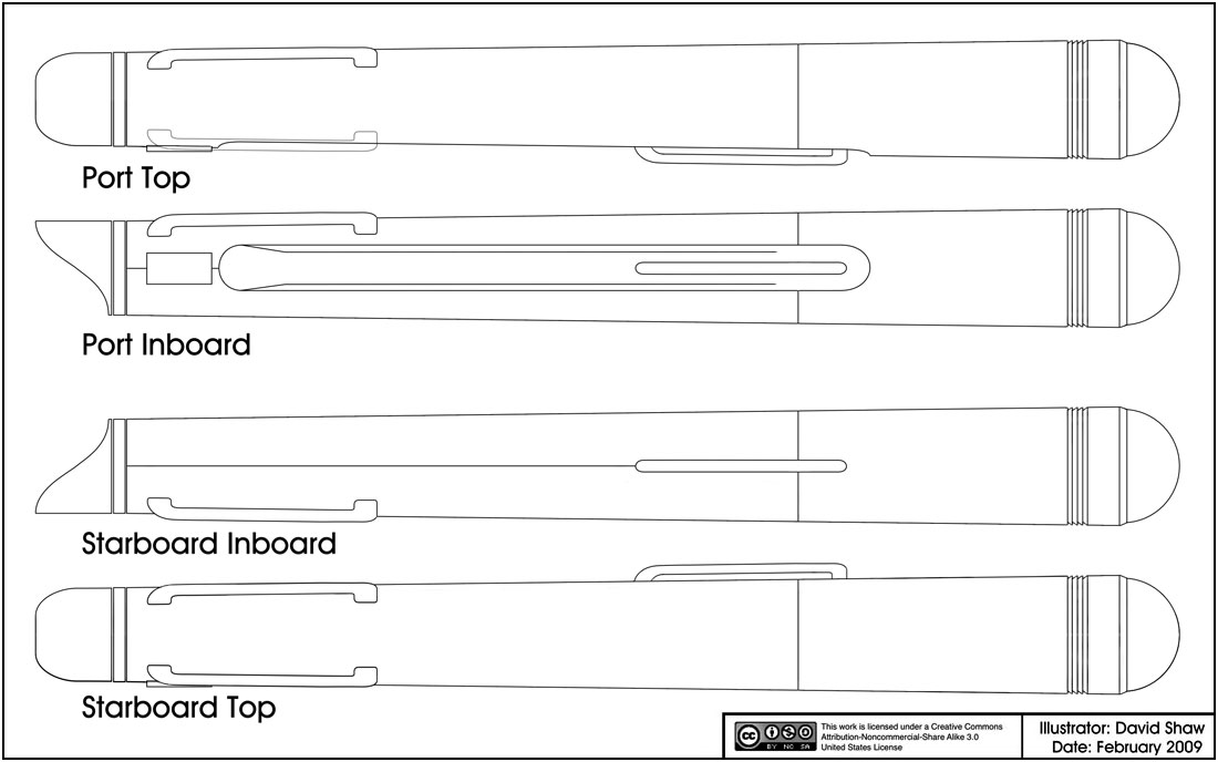
Here are top and inboard views of where I'm at in my studies of the models nacelles.
Well, you'll have a larger diameter of the structure to work with, so I'm sure that'll help. The shortening of the structure also cut down it's overall diameter.I'm rather gratified that Shaw's doing the pilot version of the ship, since the resolution of the bridge question in my plans hinges upon how well the bridge fits under that dome in the pilots.
It'll probably still need some tweaking to fit in a forward facing direction, but I need to know how much tweaking is needed.
Oddly enough this reminds me of a part of history I was rather surprise to learn.A case in point. Somewhere upthread it's mentioned that the scaling of the filming miniature actually comes out to about 944ft. for a real ship. Do you stick with that or just scale up the ship to 947ft. while retaining all the exact shapes, contours and proportions? Or did I misunderstand what I read?
I (like others) believed that the original US Navy frigates followed Joshua Humphreys designs very closely, and that frigates of the same rate of those original six would be pretty much equivalent to each other. While discussing this subject with aridas I was informed that the builders of the Constellation had modified the design and made her faster than her sister ships.
The ideal designs that Jefferies made aren't fully reflected in the models. And considering that the Enterprise is actually four large pieces connected by supports, it shouldn't be surprising to find that those pieces aren't in their originally intended positions relative to each other. Beyond the overall length issue, there is the fact that both models have their nacelles closer together than Jefferies had specified.
But we are really talking about half an inch in difference on the actual model. Move the nacelles back that half an inch and you'll get the 947 foot length.
Where did that half an inch go?
Most likely it was a compromise needed for the construction... and there were lots of compromises made. Remember, the model was late (which is why the 33 inch model was used for most of the effects), but they needed the big model for the most important effects shot in The Cage, the zoom-in on the bridge (which was to sell the size of the Enterprise to the audience).
____________
One of those interesting things about the construction of the 11 foot model is that the starboard nacelle doesn't have the trench on it's inboard side like the port nacelle. During the series the trench was actually painted on, but when the Smithsonian got the model they painted over that detail (among others) before putting the model on display.
Here are top and inboard views of where I'm at in my studies of the models nacelles.
- Status
- Not open for further replies.
Similar threads
- Replies
- 2
- Views
- 1K
- Replies
- 0
- Views
- 294
- Replies
- 192
- Views
- 28K
If you are not already a member then please register an account and join in the discussion!