Star Ship Polaris

Discussion in 'Fan Art' started by aridas sofia, Mar 3, 2008.

  1. Admiral Buzzkill

    Admiral Buzzkill Fleet Admiral Admiral

    Joined:
    Mar 8, 2001
    In Lightwave each surface has its own smoothing angle; two groups of polygons adjacent to one another on a sphere, for example, can have different degrees of smoothing. There may be an equivalence there; that said I've never seen any reference to smoothing groups in Lightwave, but many assertions that it's not used in either LW or in Modo prior to 501.

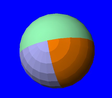
    Here are surfaces set to no smoothing, 15 percent and 90 percent. The polygons are contiguous and welded together.

    [​IMG]

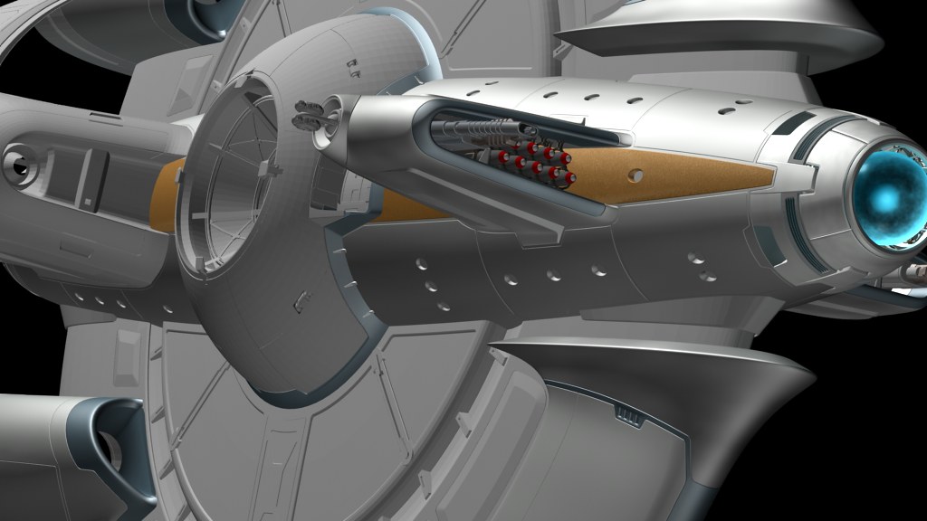
    As I said, the parts of the model I've converted and applied basic textures to look fine. I've seen a number of models, including some I've built, converted to and from LW/MAX and they always look a little different but the conversions don't seem to be problematic.
     
    Last edited: Nov 13, 2012
  2. Vektor

    Vektor Rear Admiral Rear Admiral

    Joined:
    Mar 30, 2001
    Location:
    Spokane, WA, USA
    In Max, you simply assign individual polygons to one or more "smoothing groups." If two adjacent polygons have a smoothing group in common, they are shaded into a smooth surface regardless of the angle between them. Smoothing can be automatically applied according to angle thresholds or manually on a per-polygon basis. Either way, it boils down to smoothing groups.

    Here is an example of how I modeled the panel lines and most other edges on Polaris:

    [​IMG]

    The tops and sides of each panel are all assigned to smoothing group 1 and the bottom of the trenches between them are assigned to smoothing group 2. This is the result when rendered:

    [​IMG]

    I've seen other people do this with 3 or 4 segments along every edge, but careful use of smoothing groups can accomplish virtually the same appearance with only 2 segments.

    Can you assign smoothing to sub-selections of polygons in a Lightwave surface or must you apply the same smoothing angle settings to the entire surface? If the former, then Lightwave may already be interpreting the smoothing groups correctly. If the latter, then you're going to have problems in certain areas. Fortunately, most objects in this model are already fully smoothed except for the trenches in the panel lines. If those present a problem, my suggestion is to break the bottom of the trenches out as separate surfaces, which should correct at least 80% of any potential problems.
     
  3. Admiral Buzzkill

    Admiral Buzzkill Fleet Admiral Admiral

    Joined:
    Mar 8, 2001
    Sure, in LW the top and sides of the trenches, the bottom of the trench and probably the surrounding plate are just assigned different surfaces.
     
  4. Vektor

    Vektor Rear Admiral Rear Admiral

    Joined:
    Mar 30, 2001
    Location:
    Spokane, WA, USA
    Did that happen automatically when you imported the OBJ file or will you have to do it manually? There are a LOT of those kinds of edges on this model. A significant portion of the time I spent building it was invested in smoothing those edges correctly.

    Any chance you could do a render of the same part of the model I showed above? That's the outer surface of one of the curved "ring fins" that branch off the booster engine housings. I'd just be curious to see what it looks like in Lightwave.
     
  5. Gepard

    Gepard Vice Admiral Admiral

    Joined:
    Oct 20, 2007
    Lightwave doesn't have per-vertex smoothing groups. The smoothing angle is tied to the material and is controlled from the same panel as other material properties like specularity and color. The only way to have two different normal angles on adjacent geometry is to assign two different materials to it, alas.

    It's one of the few areas where Lightwave is notably inferior to other 3D packages.
     
  6. Vektor

    Vektor Rear Admiral Rear Admiral

    Joined:
    Mar 30, 2001
    Location:
    Spokane, WA, USA
    Well, what about separating the bottoms of the trenches into a separate object or "part" or whatever Lightwave calls it? Even in Max, adjacent polygons with the same smoothing group are only smoothed if they are part of the same object.

    I actually considered doing this myself, mostly for ease of material assignment.
     
  7. Tom Hendricks

    Tom Hendricks Vice Admiral Premium Member

    Joined:
    Jun 7, 2004
    Location:
    Tom Hendricks
    Without knowing the whole background of Polaris, could the sail-less Polaris be the Polaris before its military upgrades? The Polaris was a nice, quality civilian ship before the military put all the weapons and the sails on it. Just a thought...
     
  8. Admiral Buzzkill

    Admiral Buzzkill Fleet Admiral Admiral

    Joined:
    Mar 8, 2001
    Setting the plate surface smoothing to a very high value - 179.5 - and making the bottom of the trench its own surface with no smoothing seems to work pretty well.

    The Navy put weapons and probably some hardened sensor and communications gear on the ship and converted a lot of the laboratory space. The overall design of the ship with its sails is original, though.
     
  9. Vektor

    Vektor Rear Admiral Rear Admiral

    Joined:
    Mar 30, 2001
    Location:
    Spokane, WA, USA
    My unofficial rationale behind the "sails" is that they were a pseudo-experimental modification to the standard FTL drive system to extend its range and accuracy. In essence, they capture and focus the spatial distortion from the drive spheres, enabling it to jump much further than other ships in its class and much more accurately.

    Unfortunately, there are two downsides to the technology:

    1. The sails are rather fragile and vulnerable to misalignment, potentially resulting in wildly inaccurate FTL jumps.

    2. The sails are virtually opaque to radiant energy, trapping heat in the power coils surrounding the saucer. This is why the sails are left partially open much of the time.

    I'm thinking the sails were one of those "good idea at the time" kind of things that came and went fairly quickly in the evolution of ship design. They are still, pound-for-pound, the longest range, most accurate FTL drive systems ever built, but too high-maintenance to justify on most designs unless you really need those capabilities.
     
  10. Admiral Buzzkill

    Admiral Buzzkill Fleet Admiral Admiral

    Joined:
    Mar 8, 2001
    Vektor graciously suggested that I post progress images of the model conversion here as I go. I'll do that as I have the opportunity, with a couple of caveats.

    Vektor sets a very high standard as far as working renders go - his images are beautiful - and he's an expert at lighting. What I'll post are pretty much quick renders I make of various angles on the model for my own reference as I work.

    The model was exported to an OBJ, which LightWave imports with a single surface, the LW default, which is the unsmoothed light grey that you see on most of the model here. All surface/texture information is lost. I've approximated some of the materials that Vektor had applied, again for reference.

    The basic conversion is about 20 percent complete at this point. Vektor's mesh is so well organized, including meaningful object/part names and so the process is pretty straightforward and fun. I haven't started trying to refine the surface settings or apply any texture maps, yet.

    So with all of that said:


    [​IMG]

    BTW, the rendering and animation for the show is being done by Neo F/X, so my severe limits as a CG artist shouldn't be of any concern.
     
  11. Vektor

    Vektor Rear Admiral Rear Admiral

    Joined:
    Mar 30, 2001
    Location:
    Spokane, WA, USA
    Looks pretty clean to me, although there are a number of parts missing like the lander modules, the maneuvering thrusters and various greebles. I assume those were deliberately left out of the rendering for some reason. From what I can see, the panel lines appear to be smoothed coorectly. Did they come in that way or did you have to tweak them?
     
  12. Admiral Buzzkill

    Admiral Buzzkill Fleet Admiral Admiral

    Joined:
    Mar 8, 2001
    I worked that out based on our discussions here - very high smoothing for most surfaces, with low or no smoothing for the trenches.

    It's a very efficient way of doing things, but frankly requires more detailed planning in the modeling process than I'm used to. Now that I know it, I have managed to put it to work on some of the new detailing for Saladin, though.

    After converting it I'm surfacing and reassembling the model a few parts at a time. So there are many missing parts right now.

    I'm working on getting a little "plasma" thing going for the drive spheres.
     
  13. Vektor

    Vektor Rear Admiral Rear Admiral

    Joined:
    Mar 30, 2001
    Location:
    Spokane, WA, USA
    You know what I thought would cool for those drive spheres, just a hint of a boiling water effect. If I recall Aridas' original concept correctly, there were supposed to be swarms of artificial singularities winking in and out of existence inside the spheres. I even thought of taking some video of a pot of boiling water to create an animated texture for them, probably combined with some plasma or energy streamer effects, but I never got around to it.
     
  14. Redfern

    Redfern Rear Admiral Rear Admiral

    Joined:
    Sep 28, 2006
    Location:
    Georgia, USA
    Kind of a quantum lava lamp? ;)

    I know; I know. What you describe is far more energetic, but that was the thing thing that popped into my mind when reading your post.

    Seriously, that would be a d*mn wicked effect if realized.

    Sincerely,

    Bill
     
  15. Vektor

    Vektor Rear Admiral Rear Admiral

    Joined:
    Mar 30, 2001
    Location:
    Spokane, WA, USA
    There's a scene in the script where the engineering section appears in the background of an on-screen communication, so I decided to see what I could come up with design-wise. With apologies to Aridas Sofia for once again diverging from his original design, here's my take on what the main engineering section might look like in cross-section:

    [​IMG]

    There are several important things going on here:

    I've located engineering further toward the aft end of the ship, closer to the main engines and the aft "toroidal loop interconnect." Early on I posited a large ring or loop within the saucer that intersects the connecting conduit between the drive spheres at two points. I had the vague idea that this loop is the main component of a toroidal fusion reactor for generating most of the ship's power, and that it is also connected directly to the FTL drive system. There would also be a power distribution manifold located dead center of the central sphere between the tips of the two lander modules, branching out at the four 45 degree angles as suggested by the details on the outer hull. And, of course, there would be another toroidal loop interconnect toward the front of the ship. All of this started from Aridas' original concepts and cross-sections, but I've taken some considerable creative license with it to try to reconcile all of the exterior modeling work.

    I'm taking advantage of some of the space outside the central fuselage for various purposes. Engineering extends into the main engine pylons to port and starboard and also into the saucer area both ventral and dorsal. I've also modified the original concept of zero-gee transit tubes. Instead of two staggered shafts within the fuselage, I'm using four just outside the fuselage where it intersects with the saucer. Two of these tubes are elevator lifts and the other two are switchback gangways. Given that this ship has the ability to land on its tail on a planet's surface, I thought these made more sense. They would be easier to build and film as practical sets, should the opportunity ever arise. And they're no longer taking up valuable space within the fuselage.

    This isn't absolutely final, but I'm fairly happy with the direction it's headed.
     
  16. Admiral Buzzkill

    Admiral Buzzkill Fleet Admiral Admiral

    Joined:
    Mar 8, 2001
    I like this, but I think I should send you a temp composite that Maurice did to give you a sense of how the shot's laid out and what we need to be going on in that angle.
     
  17. Vektor

    Vektor Rear Admiral Rear Admiral

    Joined:
    Mar 30, 2001
    Location:
    Spokane, WA, USA
    I actually have an email half-written asking for exactly that. I look forward to seeing it.
     
  18. Maurice

    Maurice Snagglepussed Admiral

    Joined:
    Oct 17, 2005
    Location:
    Real Gone
    Dennis: send an email to Vektor and me and I can send him reference for just about anything he needs.

    As I recall, we discussed steering hard to port from anything that looked like a Star Trek type warp core/intermix/shaft.
     
  19. Vektor

    Vektor Rear Admiral Rear Admiral

    Joined:
    Mar 30, 2001
    Location:
    Spokane, WA, USA
    So I started working on some design ideas for the engineering section, using an actual greenscreen background plate (or foreground plate in this case) from the production. This was my first concept, derived from the earlier cross-sectional sketch, with a heavy dose of Trek warp core/intermix shaft thrown in:

    [​IMG]

    As it turns out, the Trek overtones were not what Dennis and the gang wanted to go with for this, which was fine. I'm nothing if not adaptable. This morning I sat down and started working on round two, blending in some elements from an unused Forbidden Planet set they had been using as a temporary backdrop, and generally trying to get away from the central warp core look. I took screen shots throughout the day and thought I'd go ahead and post the progress so far for your viewing enjoyment. This design hasn't been approved yet so it's likely some changes will be in order, perhaps even another concept entirely, but it's going to make a good addition to my portfolio either way.

    [​IMG]
    [​IMG]
    [​IMG]
    [​IMG]
    [​IMG]
    [​IMG]

    And finally, here's a version that's been cropped to something more like they would actually use for this particular shot:

    [​IMG]

    Please note that this had only progressed to the underpainting stage with nearly all of the original linework still visible. To fully complete this, I would do a further paintover, removing the linework entirely and polishing the entire piece extensively. I think this is about as far as I'm taking it at the moment, however, until I get some official feedback.
     
  20. sojourner

    sojourner Admiral In Memoriam

    Joined:
    Sep 4, 2008
    Location:
    Just around the bend.
    Is that a binary clock from Thinkgeek on that set piece?

    Oh, great art as usual Vektor!