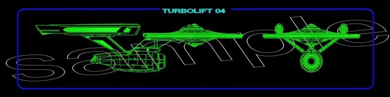
We're working on the turbolift for our fan film, but we're looking for the Enterprise diagram that goes in the frame at the back of the lift. Anyone seen one like that? TIA
-
Welcome! The TrekBBS is the number one place to chat about Star Trek with like-minded fans.
If you are not already a member then please register an account and join in the discussion!
You are using an out of date browser. It may not display this or other websites correctly.
You should upgrade or use an alternative browser.
You should upgrade or use an alternative browser.
Enterprise Turbolift Diagram
- Thread starter Potemkin_Prod
- Start date
Enterprise A
Could make one for you easily, but it has to wait untill tomorrow. If so, any preferred size in pix?
Tom's quite right. Enterprise-A type ship (Potemkin).
It's going to print at 48" wide by 12" tall. I'd prefer 300 dpi, but can settle for less if need be.
Thanks!
Looks awesome. Check your PM. Thanks!!!

Have seen plenty of clips of that scene in TMP, but never could find a decent version of it. The one provided by wjaspers captures the essence and feel of the diagram.
I should have some pictures of the turbolift set over in Fan Films by the end of the weekend.
I should have some pictures of the turbolift set over in Fan Films by the end of the weekend.
Nice, but when you scroll up, it says Enterprise-A
The thing I don't like about the one posted by wjaspers is that it's just a drawing of the ship's outside and gives no indication of where you are or where you can go.
Well that is how it shows up in the Ent-A, but you're right, I never understood why they did it that way, there is no reference at all where you are or should go.
There's a bright dot to indicate where you are. This would be problematic if we were to attempt the same. I like what you sent us, and will post pics Monday night of it in place.

Did the designer really intend there to be that many turbolift stations throughout the ship? I mean, they're everywhere! Even where they couldn't possibly be like inside the open space of the cargo bay!
However, I do like the way that the saucer top-view is assymetrical - it gives the impression of machinery which needs to be skirted around.
")
I'm pretty sure some of the detail you see in the side view are text labels that end up looking like shafts because they're out of focus.
Did the designer really intend there to be that many turbolift stations throughout the ship? I mean, they're everywhere! Even where they couldn't possibly be like inside the open space of the cargo bay!
However, I do like the way that the saucer top-view is assymetrical - it gives the impression of machinery which needs to be skirted around.
Last edited:
I'm pretty sure the diagram on the left has very few labels. Most of those are logical places for the turbolift to be, and probably match one of the blueprint sets to some degree.
It worked for me, just as the diagram did on this set:
http://www.projectpotemkin.com/taking_on_the_turbolift.htm
http://www.projectpotemkin.com/taking_on_the_turbolift.htm
That's very well done, wjaspers. I own the actual translight from the set, and your version captures it nicely.
Concerning the turbolift stations, the diagram need not be taken literally. Look at a map of the London Underground and you'll see what I mean. Relative positions are more important than literal.
Concerning the turbolift stations, the diagram need not be taken literally. Look at a map of the London Underground and you'll see what I mean. Relative positions are more important than literal.
Similar threads
- Replies
- 41
- Views
- 2K
- Replies
- 43
- Views
- 11K
- Replies
- 1
- Views
- 2K
- Replies
- 10
- Views
- 2K
If you are not already a member then please register an account and join in the discussion!