• Welcome! The TrekBBS is the number one place to chat about Star Trek with like-minded fans.
    If you are not already a member then please register an account and join in the discussion!

my take on the TMP-E

^ the only reason those options arent open to this is that all the components are already cut into the lathed surfaces, its modeled as solid objects, but they are also hollow, like the cutaway earlier showed. and the bridge, neck, impulse are all a part of the saucer, and the same with the parts on the secondary hull.

you can see what i mean here on this cutaway
capture_12232009_172616.png


working this way makes it much easier in AutoCAD, but makes converting to other formats terrible :(
 
Ah....another TMP Model Project.
Even though the curves of the saucer (ventral) are a bit too steep and bulbous this is...beautiful....especially the engine work.
 
ty!

do you think you could come up with some sort of images to show how you see the curvature down there? i have explicit reasons for every shape being just as is, but when it comes to this model i actually love being proven wrong!!! it only helps make a more accurate rendtition :techman:

i work from a library of over 700 unique documentary photos of the model, not to mention screenshots etc...
 
:(:(:(:(:(:(:(:(:(:(:(:(:(:(:(:(:(:(:(:(

ok, it looks like just completing it in CAD the way i had been then rendering over in max is definately OUT... i added a single light source this morning and spent several hours attmpting to render up a shot to overlay on the full size version of this image
Profiles_08101_1.jpg

to show how unless you are looking at it dead on, you cant really tell the saucer's underside actually has such a deep curvature, buuuuuuut.........

i think my computer is about to go on strike... without fail, no matter what settings i tried, or how much sys-resources i freed it would choke and max would fatal-error out with one excuse or another just as it would be finalizing the render :scream:

i was only able to get 1 small test render to come out, and the texture on the saucer bugged on it. but here's the result
ani01.gif


i'll have to gut all the "innards" to simplifiy it. no biggie to do, just tedious...
 
I've been constantly drawing, drafting, modeling the Refit for well over a decade now. its hands-down my all time favorite model/vessel (from any genre)
this latest version has gone through many many evolutions, this is still a WIP so far created all in AutoCAD. i had been wanting to get it into Max for quite a while, but was having endless conversion difficulties :(

that is untill last week! i finally had someone here at the house who actually knows modeling and was able to help me get it properly transitioned :techman:

here's a couple quick renders of the new Max version


C2-032.png


i originally planned this to be a complete 3d-cutaway deck plans and all, but that was back before i discovered CTM's thread and his attempt at the same thing! i think i'll just let him finish first!!!!! haha

:(:(:(:(:(:(:(:(:(:(:(:(:(:(:(:(:(:(:(:(

ok, it looks like just completing it in CAD the way i had been then rendering over in max is definately OUT... i added a single light source this morning and spent several hours attmpting to render up a shot to overlay on the full size version of this image
Profiles_08101_1.jpg

to show how unless you are looking at it dead on, you cant really tell the saucer's underside actually has such a deep curvature, buuuuuuut.........

i think my computer is about to go on strike... without fail, no matter what settings i tried, or how much sys-resources i freed it would choke and max would fatal-error out with one excuse or another just as it would be finalizing the render :scream:

i was only able to get 1 small test render to come out, and the texture on the saucer bugged on it. but here's the result
ani01.gif


i'll have to gut all the "innards" to simplifiy it. no biggie to do, just tedious...

Take a look at the link.
When I saw your version I detected this almost immediately and it probably one of the hardest things to get right on the design.

I guess it's a nitpick.
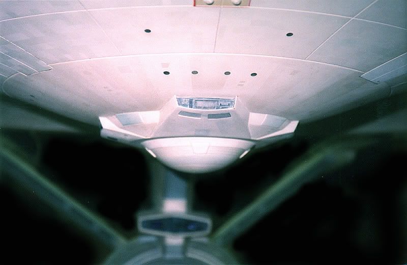
The light and sensor cluster that hanges bellow is actually on a more of flatten plateau than a dome (like in yours)

http://www.cygnus-x1.net/links/lcars/blueprints/enterprise-deck-plans-sheet-3.jpg

The effect is the same difference between the TMP Enterprise and the TOS Enterprise. The dome on the bottom on yours looks better for the TOS Enterprise.
 
now i see what you're talking about.

you believe that the hull flattens out on the bottom the way it does on the top. i can assure you that is just an optical illusion created by the sensor cap itself, and the way the "fingers" stretch out in the cardinal directions.

the sensor dome is one of the last parts i had been working on, so i added it to the model and took this shot for you.
a3.gif


you can see how once the cap is placed the "flattening" illusion is created. that tiny bit of flattening illusion also adds a great deal to making the saucer look much wider (or longer) depending on what angle you're looking from.

on the actual model the hull is cut out down there, to allow access through the dome to lighting/wiring etc. but i'm 95% confident that before the hole was cut, it was shaped with the full bowl shape.

Okay I'm willing to buy that...and I considered that tooo...but
Okay listen, I was just going on memory...

Take a look at these shots of my scale model of the Enterprise that' I've never put together.

dsc03118c.jpg


dsc03119tf.jpg


Okay so this not only shows a flat under side. (for your consideration but>>>> It also shows that the domed hull isn't as deep are tall (it would seem as in the beautifully sexy rendered version you've posted....

What do ya think?
 
Take a look at the link.
When I saw your version I detected this almost immediately and it probably one of the hardest things to get right on the design.

I guess it's a nitpick.
The light and sensor cluster that hanges bellow is actually on a more of flatten plateau than a dome (like in yours)

http://www.cygnus-x1.net/links/lcars/blueprints/enterprise-deck-plans-sheet-3.jpg

The effect is the same difference between the TMP Enterprise and the TOS Enterprise. The dome on the bottom on yours looks better for the TOS Enterprise.

Here is a better one:

http://www.cygnus-x1.net/links/lcars/blueprints/star-trek-the-motion-picture-sheet-1.jpg

From this it looks like Anystar is right about that.

Think it is better to look at the pictures of the Ent, where you can see that is a perfect dome. Always nice these orthos, just need to use the right ones.
 
i know thats one of the best scale models there is, but it really doesnt do justice to the 8' filming miniature.

here's a couple of the old B&W pics taken during initial construction, and a couple downsized closeups of the sensor array.
Profiles_038.jpg

Saucer-Under_014.jpg

Sensor_040_1.jpg

Sensor_044_1.jpg

Sensor_046_1.jpg

Sensor_048_1.jpg


i really wish i could post some pics of the orthographic ref's i use myself, it would clear everything up instantly...

but because of those refs i dont even post images of my own blueprinted c2 plans anymore :(...... last time i did i caught all kinds of hell from an unnamed small-minded person claiming all i do was plajarize the original creator's work...
 
Well, I think I stand corrected...
Thanks for entertaining my concerns.
But is it really that far from the Saucer Edge? That far down?
 
it does seem rather deep in orthographic projection, but its my best guesstimate.

however, you rarely see it from that perfect-angle. with only a degree or two of pitch you either loose sight of it underneath the protruding edge of the saucer, or the profile is lost by the horizon of the backside edge when viewed underneath.
 
Well you'll know in the end because in CAD you can recreate those exact angles and camera focal points. If it sticks out too far you'll know it. I guess you'll just have to finish it to find out for sure.
 
in the end, it may end up being too low. we'll just have to wait and see :)
i want to finish off my dry-dock and my x-wing before i get back into this one however.

there is another reason i want to avoid moving the depth too much. its actually a hollowed out model, and i've already modeled in the floorings for the deck plans. i already have the lowest saucer deck and the sensor controll room shortened to fit everything in nicely. moving it any further will either force me to eliminate a deck entirely down there or screw up the ceiling height on a 3rd. :(

i try to fall back on the 8' miniature as a final word for most parts, but i have made allowences here and there for better design-flow of internal structures. for example, placement of the eng-hull's airlocks, the height of the neck, and also the depth of the saucer.
 
in the end, it may end up being too low. we'll just have to wait and see :)
i want to finish off my dry-dock and my x-wing before i get back into this one however.

You're a good designer, AnyStar. You have a distinctly different attitude than others.

there is another reason i want to avoid moving the depth too much. its actually a hollowed out model, and i've already modeled in the floorings for the deck plans. i already have the lowest saucer deck and the sensor controll room shortened to fit everything in nicely. moving it any further will either force me to eliminate a deck entirely down there or screw up the ceiling height on a 3rd. :(
Ah...
You're sort of committed to it. Gotcha. CAD is difficult enough, isn't it. I've certainly struggled with it.

i try to fall back on the 8' miniature as a final word for most parts, but i have made allowences here and there for better design-flow of internal structures. for example, placement of the eng-hull's airlocks, the height of the neck, and also the depth of the saucer.
Yeah, CTM had similar difficulties but...(don't tell hi I said so) Yours from the outside is quite superior in detail and that's because I believe you modeled the outside first.

P.S
I could use some help if you know any modeling techniques for doing these complex shapes in CAD...I need to know just what CAD doesn't and does like because I'm losing my mind.

Solid modeling is a pain.
I've learned that the Loft Commander sub commands like Cross-section, Path and Guides like and dislike different things. But I'm trying to do my secondary hull and it's a doozey.

I'm waving the White Flag here.

Here is my thread. http://www.startrekmovie.com/forums/showthread.php?t=8426
 
i still love modeling in CAD, but its a completely different beast than most 3d modeling programs.

one of the most common commands/techniques i use in CAD is like you mentioned the lofting. primarily i'll work in sectionals, and when im done with the wireframe i'll turn cross sectional segments into regions, and either loft/extrude/sweep/revole to get the shape i need.

since control points are nearly non-existent in AutoCAD your only option for editing past that are boolean opreations, which luckily work far better than in Max. believe it or not, when i'm modeling in Autocad i'm constantly tweaking my objects, then making "moulds" of them with a series of booleans. because in order to keep refining you have to keep manipulating, but the way AutoCAD "remembers" the original shapes of your objects (despite deliberately turning off the option to retain it) it will eventually bug.

this is an old version of the fuselage for my x-wing project. you can see the evolution of the different parts, and the final digital "buck" from which i can just pop in a box shape and instantly boolean the final product to continue refining. its also in 4 parts, male and female so i could extract upper and lower halves separately.
001.png

002.png

003.png


about 60-70% of my CAD models are created by this process.

you also have to plan out your "intermediate" steps and curves in advance as well with polylines or arcs, and use them with the path or guide options. it is always trial and error for me getting some of the more complex shapes. and usually takes several tries.

above all, the best tip i can give you for modeling in CAD:
when you get frustrated trying to get the shape you want (and you WILL) just set it aside and move on to a different part for a while. :devil:
 
Yeah, CTM had similar difficulties but...(don't tell hi I said so) Yours from the outside is quite superior in detail and that's because I believe you modeled the outside first.

You'll get no argument from me on that point. I know my exterior is not as accurate - I knew that would be the case from the moment I decided to build it from the inside out. This is outstanding work AnyStar. Again, please don't wait on me to start working on your interiors - the more the merrier.
 
P.S
I could use some help if you know any modeling techniques for doing these complex shapes in CAD...I need to know just what CAD doesn't and does like because I'm losing my mind.

It's just as AnyStar says "trial and error" "and usually takes several tries"

Maybe one tip: try to avoid solids created by using part of elipses.

Solid modeling is a pain.

No it isn't :)

If you care, here is a link to my models ALL created in Acad and imported into 3dsmax, made up in solids for at least 99% (acad2004 did not have a loft command so sometimes I used a meshpart), my Ent is on page 2 and 3.
http://s131.photobucket.com/albums/p298/wjaspers/

I'm trying to do my secondary hull and it's a doozey.

I'm waving the White Flag here.

Looked at your thread, and the Youtube vids, but it was very hard to make out how the sec hull should look like, ie give you a tip on how to do it.


Anyhow, I hope AnyStar's other models will be finished soon, so I can see some updates here :)
 
If you are not already a member then please register an account and join in the discussion!

Sign up / Register


Back
Top