-
Welcome! The TrekBBS is the number one place to chat about Star Trek with like-minded fans.
If you are not already a member then please register an account and join in the discussion!
You are using an out of date browser. It may not display this or other websites correctly.
You should upgrade or use an alternative browser.
You should upgrade or use an alternative browser.
Searching for closeup view of this Enterprise diagram
- Thread starter retronaut
- Start date

This diagram was discussed in great detail over in the ASAP Prop Forum, IIRC. I had noticed that this diagram differed from the others (such as the "hull pressure compt's") on the bridge station displays. As such, this diagram is unique thanks to the shape of the saucer, and short nacelles, etc. I, and some other posters did an exhaustive comparison of the different displays in the hope someone could produce an acrylic version available for sale. The discussion ended before anyone would commit to the project. Besides, none of the attempts looked right-on because the source images weren't clear. I will try to find that thread.
BTW, to answer your question -- in our search of episodes, there was no better shot of the display than the one you posted. The fuzzy view was the best anyone could find.
Edit: Found the link . . .
http://propreplicas.yuku.com/topic/7799
BTW, to answer your question -- in our search of episodes, there was no better shot of the display than the one you posted. The fuzzy view was the best anyone could find.
Edit: Found the link . . .
http://propreplicas.yuku.com/topic/7799
Last edited:
You need to have an account to view that page.
Also, some of the links in the last message on the thread are dead.
You need to have an account to view that page.
Also, some of the links in the last message on the thread are dead.
Nothing's ever easy, is it?
Last edited:
Okay, I'm now mildly curious... are you saying that there is a good reason for reverse engineering this diagram? That there is a good reason to spend time re-creating all the actual details (which is time consuming) rather than just sketching the basic details (which has been done)?... and some other posters did an exhaustive comparison of the different displays in the hope someone could produce an acrylic version available for sale.
My study of the diagram documented all the aspects needed for an accurate re-creation... but I saw no reason to spend more than a few minutes in creating a rough sketch of the thing.
Is there a good reason for more effort?
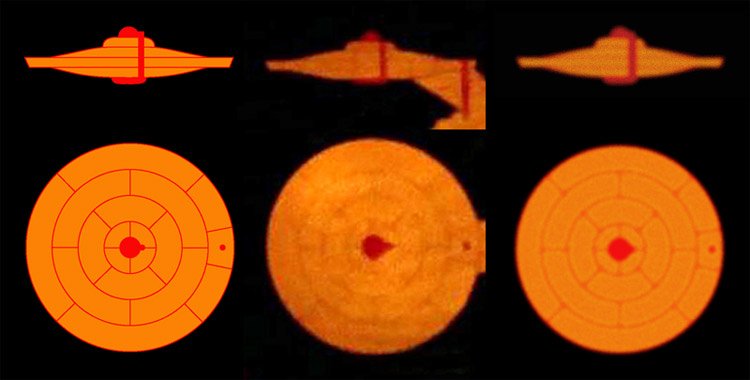
My only observation is that the diagram on that panel is unique, includng w/ regard to the saucer section lines in the vertical view. Also, the meaning of the dark orange areas is not clear, especially in that the entire bridge is shaded dark orange.
I wasn't aware of the prior discussion, but it would be great to find a clearer photo of the original plaque, and to nail down the details.
Okay, I'm now mildly curious... are you saying that there is a good reason for reverse engineering this diagram? That there is a good reason to spend time re-creating all the actual details (which is time consuming) rather than just sketching the basic details (which has been done)?... and some other posters did an exhaustive comparison of the different displays in the hope someone could produce an acrylic version available for sale.
My study of the diagram documented all the aspects needed for an accurate re-creation... but I saw no reason to spend more than a few minutes in creating a rough sketch of the thing.
Is there a good reason for more effort?
Its called being anal.
")
Seriously now, that thread was a waaaaay serious attempt to get the diagram 100% perfect. It was, of course, impossible given the source material. That's probably why the discussion abruptly ended with no resolution.
I had started that thread to get info on that display, which I thought was a very unusual depiction of the ship. I was wondering if it could have been created even before the final design of Enterprise was nailed down. The other posters were having fun playing with it to see what they could come up with. Maybe in the end they decided is was wasted effort and dropped it.
Last edited:
That is an easy enough question to answer... yes.... I was wondering if it could have been created even before the final design of Enterprise was nailed down...
The bridge graphics that represent the Enterprise are all based on illustration work from October of 1964. The only copy of the final design of the Enterprise was finished on November 7, 1964 and was used for both models (the 33 inch model was started right away, the 11 foot model was started on December 8, 1964). The bridge set was started around mid November and the first live action filming was done on the set on November 30, 1964 (and included the graphic in question).
Even Datin, who was hired to build the models on November 4, 1964, was originally given an early set of plans for the models. And it seems that the hull graphics for the models were originally drawn on one of those early plans too (as none of that type of thing appears on the final construction plans).
But I'm sure you guys reached all these same conclusions and made a hyper accurate representation of the diagram, so there is obviously nothing new I could add.
You've got an evil streak in you....
I didn't think that was evil... but until people say what they want or how far they had gotten, I can only assume they've done a good job and congratulate them for... well, what I don't know.
But fine, I've looked at the thread (I hate signing up for additional forums if I don't have too), which is from 2006, and see they didn't get all that far. Someone could have just said "they didn't get very far" and then I'd be happy to help.
People said it was impossible to make plans of the 33 inch model, it wasn't. People said that re-creating Jefferies original construction plans would be impossible, but great strides were made towards that. And here Green Shirt said this was "impossible given the source material", but I've documented way more information on that diagram then that thread had.
I enjoy taking stabs at things considered impossible, but I'd rather know that I'm not reinventing the wheel with my efforts. And I shouldn't have to sign up for a forum I doubt I'd frequent to find this out.
I don't consider any of that evil... but charging for doing a re-creation might be debatable though.
I'd say anyone who really wants to reverse engineer this drawing could do worse than to look at the hi-def caps on TrekCore. I looked at few last night and I could more plainly see a line of two on the image than are clear here. If you have the show on a hi-def video format, you could go through carefully and look for shots where the diagram in plainly visible.
In the case of the still above, "The Naked Time".
http://tos.trekcore.com/hd/albums/1x04hd/thenakedtimehd0650.jpg
http://tos.trekcore.com/hd/albums/1x04hd/thenakedtimehd0650.jpg
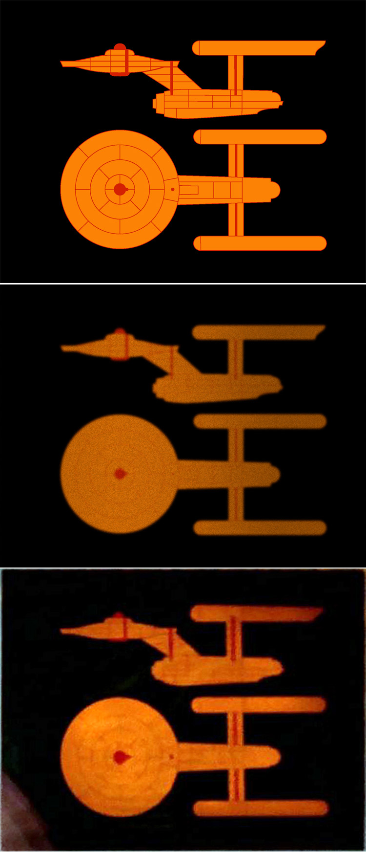
I don't think it was ever going to be all that difficult... I mean here is a comparison of a five minute clean up of the primary hull of my sketch from last March compared to the screen shot shown in the first post in this thread...I'd say anyone who really wants to reverse engineer this drawing ...
I've nailed down the elements of the top view of the secondary hull in my earlier sketch, but it is the secondary hull profile that would take a little effort to match up the internals nicely.
The main thing seems to be not to get hung up on the Hull Pressure Compartments diagram because they seem to have a number of striking differences in line placement.
Of course depending on how closely this diagram's curves were to one of the early set of plans, we might have some idea why the 33 inch models primary hull curves are so different. Datin may have started building that model before receiving the final plans on November 7th or 8th, as he was given an early set on November 4th that outlined what he would be building. The primary hull being such a hard piece to make, someone may have opted to stay with that earlier design rather than start over with the final plan's curves for that piece. Maybe that early set of plans resembled what we are seeing here.
All just idle speculation of course.
 :rolleyes:")
Maybe that graphic is something akin to a subway map? Not drawn to scale or even very accurate, but gets the job done.
My point being that the people who wanted this can do it themselves if they just look at the right references.I don't think it was ever going to be all that difficult... I mean here is a comparison of a five minute clean up of the primary hull of my sketch from last March compared to the screen shot shown in the first post in this thread...I'd say anyone who really wants to reverse engineer this drawing ...
")
Maybe that graphic is something akin to a subway map? Not drawn to scale or even very accurate, but gets the job done.
My sentiments exactly, with the vast majority of the technical schematics we've seen on screen.
Similar threads
- Replies
- 192
- Views
- 29K
- Replies
- 53
- Views
- 9K
If you are not already a member then please register an account and join in the discussion!