Another take on the Original Enterprise...

Discussion in 'Fan Art' started by Cary L. Brown, Apr 24, 2009.

Thread Status:
Not open for further replies.
  1. Cary L. Brown

    Cary L. Brown Rear Admiral Rear Admiral

    Joined:
    Oct 14, 2005
    Location:
    Austin, Texas
    Warp Reactor Concept

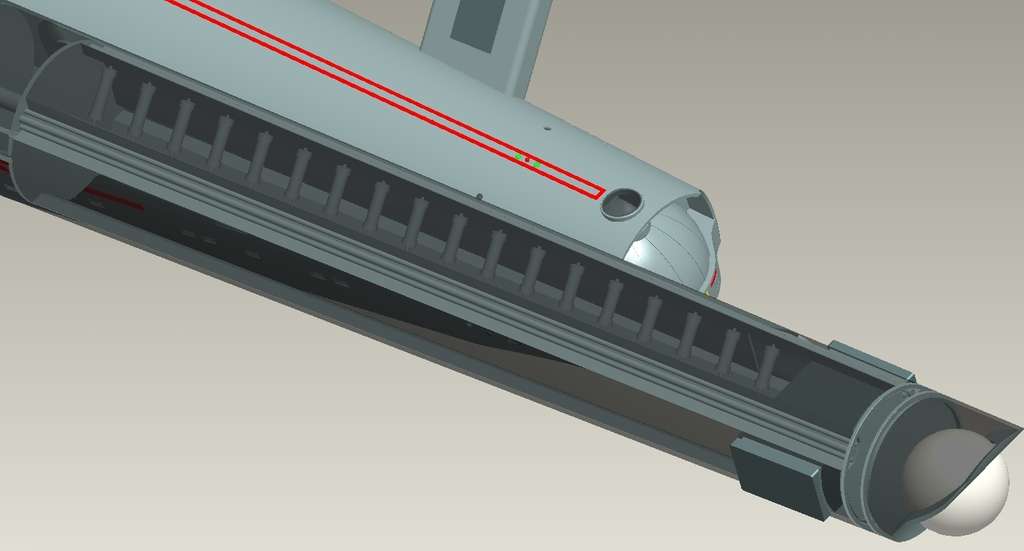
    In the nacelles, I have a series of cylindrical reactors. You can see one of those pretty clearly, below.
    [​IMG]

    Now, an in-universe explanation of what's going on here:

    ********************

    The matter (in the form of simple hydrogen), superheated by a fusion device, slightly cooled as it leaves the "control reactor," and then flowed into a distribution manifold along the central axis, is injected into each of these reactor chambers, in a closely-controlled sequence. Note that each chamber is slightly smaller than the one forward of it... this is by design.

    The antimatter is contained in a facility at the aftmost end of the nacelle (roughly "box" shaped, extending beyond either side of the nacelle body). From here, the antimatter is injected into one of four shielded antimatter transfer tubes, which are found in the four aft nacelle main structural channels. The antimatter is delivered to the reactor chambers via these manifolds.

    There are four rows of reactor chambers, spaced 45 degrees apart. All four dump half of their output into the central "reactor core feed line" where some is channeled towards the secondary hull main energizer to produce usable power for the ship, while the majority is directed aft, towards the subspace field generation device ("the sphere").

    Also found in the structural channels are two other major "plumbing" systems... a second reactor core feed line (each of which carries the other half of the individual reactor chamber row output, that which is not carried by the central core element) and a primary coolant system line.

    This gives five channels, all carrying high-output matter/antimatter reaction products (not counting the tap to the main energizer) which are used to generate the subspace field.

    The field is generated by focusing the five "streams" at the very center of the field generator sphere. The central "feed" is fixed, as are the lower two. However, the upper two can be "tweaked" by diverting a portion of their flow through an intercooler device.

    Controlling the flow... the delivery of energy... from the outer four conduits results in an assymmetrical energy field, and thus a tendency for the ship to "turn" while at warp.

    With two nacelles, the output of both nacelles can be adjusted to allow for a lateral turn. To allow for 3-dimensional manuevering, a set of intercoolers assist, allowing significantly higher energy-delivery-reduction for the upper channels. When primary m/am reaction product in these conduits is cooled significantlym, the energy flow in these upper pathways, is reduced. This causes the the effective energy field in the subspace field generators will be more significantly distorted, allowing for the ship to steer sharply upwards.

    While any of the conduits can have their flow reduced, or can be diverted to the cooling devices, the most effective means of controlling directionality within a single nacelle is through directing the upper flows through the intercoolers. This explains why the ship tends to "bank" when turning when at warp... the ship turns upwards more easily than it does downwards. If the ship had only lower-mounted intercoolers, it would be easier to "nose down."

    (The installation of additional "underside" intercoolers was "cost-reduced" out of the design, as under most circumstances this adds no additional performance yet imparts a significant mass penalty to the ship.)

    The field tends to propagate directionally from the main field generator, with a slight forward distortion. By adjusting the focal point of the field convergence in the sphere, the overall distortion of the subspace field can be controlled, but only within certain practical limits.

    Additional field stability is provided by the installation of fixed "subspace field generator coils" which are located in the gaps between m/am reactor chambers, and are charged by the adjacent two chambers. These coils do not generate a "warp" field, but support the primary field, increasing and amplifying its strength along the line-of-action of the vessel.

    *********************

    That's all I've come up with so far...

    Now I have to replicate the "reactor cores" another seven times. This is pretty simple, though, since I only had to model one, and then "pattern" it to create what you see here. I'll do the same for the "stabilizer coils" which I'm going to model as well.
     
  2. Cary L. Brown

    Cary L. Brown Rear Admiral Rear Admiral

    Joined:
    Oct 14, 2005
    Location:
    Austin, Texas
    Re: Warp Reactor Concept

    Well, I was afraid of this...

    Putting the entire "reactor system" into those nacelles brought me to the "32-bit memory brick wall."

    I've been making some preliminary plans to upgrade my system, but it looks like the 1701 layout may become held hostage to "when I get that done."

    For anyone not familiar with this... in 32-bit Windows, you're limited by the memory management to a total of 4GB of allocatable memory. If you have a powerful video card (mine has 768 of video memory), that comes out of the total. So while I have 4GB of installed physical CPU memory, I don't get to use the entire amount.

    In 64-bit Windows, the memory limit is tremendously higher. Most contemporary "CAD" machines are set up as 64-bit with 12GB or so. My work machine has 16GB.

    I COULD take this to work and do this there, but that's a misuse of company resources and I'm not inclined to get myself into hot water that way. So until I get a bit more "home" computing power, I may need to put this (like the Vega) on hold.

    FYI, the Vega also hit that "memory wall. But I was hoping that this ship would be a bit less memory-intensive. Well, it is, and it isn't. That is, I didn't ever build "guts" for the Vega's nacelles, or impulse engines, or so forth.

    Anyway, I think this is gonna give me some incentive to spend a bit more money. Ah, well...
     
  3. B.J.

    B.J. Rear Admiral Rear Admiral

    Joined:
    Jul 14, 2004
    Location:
    Huntsville, AL
    If I remember right, you're building this in Pro-E, right? Is this all in one file, or did you separate anything out into assemblies and components? I would imagine that you'd be able to at least continue working on the nacelles by themselves without having to load *everything*.
     
  4. Psion

    Psion Rear Admiral Rear Admiral

    Joined:
    Oct 19, 2001
    Location:
    Lat: 40.1630936 Lon: -75.1183777
    Please let me second this suggestion, Cary. Please work on the nacelles separately and use only the exterior in your finished project. I'm fascinated by your efforts and hope to see more of the inner workings.
     
  5. Bernard Guignard

    Bernard Guignard Fleet Captain Fleet Captain

    Joined:
    Jan 25, 2005
    Location:
    Ontario
    Great work there Cary :techman::techman::techman::techman:
     
  6. Patrickivan

    Patrickivan Fleet Captain Newbie

    Joined:
    Jul 16, 2006
    Re: Warp Reactor Concept

    Oh you're a tease! You post 2 images, and then you tell us that you may not be able to do anything for a while...

    With regards to the subspace field generation device, how would this affect your design if you were also putting together a model of the earlier nacelle design that didn't have that FGD sphere?

    In the second paragraph I quoted you in, would it be those subspace field generator coils that would work solely w/o the sphere? Or am I completely mis-interpreting your design? If that were the case, then I can certainly see the advancement in technology- leading from the less stable to the more stable field generation.

    And it's great that you're putting the power plants in there as intended. I suspected you would. I'm doing the same for a physical model I'm working on. This is good inspirational material to help me with mine.
     
  7. Cary L. Brown

    Cary L. Brown Rear Admiral Rear Admiral

    Joined:
    Oct 14, 2005
    Location:
    Austin, Texas
    Well, as a rule (when working on a "real" project) everything... down to the individual nut, bolt, washer, etc... is a part, and everything fits together into a tree-structure of assemblies and subassemblies.

    In this case, I'm using Pro/E as the modeler, but don't intent to keep it in here. In fact, none of the "pretty" renders have been made from the native Pro/E model, but rather have been imported into another package (either Maya, or more commonly, NuGraf... which, along with its subcomponent "Polytrans" is more capable of properly translating Pro/E files into other "renderable" formats than anything I've ever dealt with.

    Side note... it may cease to be necessary to do that in the not-too-distant future - as Pro/E's latest (not QUITE released yet, except as BETA) version has tossed aside the old lightray renderer (which was VERY limited) and is now incorporating Mental Ray (the same renderer typically used in many high-end 3D graphics programs). So "Translation" MIGHT become a moot point. (Or, it might not... depending on how PTC allows Mental Ray to be used within their package!)

    Right now, in my "Enterprise" model, I have the following components:

    1) Primary Hull (complete)
    2) Secondary Hull (complete)
    3) Turbolift Car
    4) Shuttlecraft
    5) TOS-style chair.
    6) Standing "Poser" figure (import)
    7) Seated "Poser" figure (import)

    And that's it. Only items which are either required to be able to be moved, or exist in a number of locations. (or both).

    That's mainly to ease the transitioning of this data into other packages. The goal has been to create the model in Pro/E generate 2D drawings in Pro/E, but tranfer the 3D solid into Maya for rendering purposes (including animation). That's "the goal" for every model I've made, not just the 1701. So I try to keep the logical structure simple, and avoid stuff that gets confusing when working with Maya's controls.

    The primary hull and secondary hull share a common coordinate system, so I only need to mate those up from that coordinate system, and if I want to separate, I only need to animate the parameters of that alignment from "zero" to whatever values I want. Turbolifts, and people and chairs and so forth are mainly just to save time and energy. And the (partially-completed) shuttle "framework" is there mainly to help with scaling for the moment.

    The "Ringship" and the Bonaventure both fit well under the 32-bit restriction, as does the shuttlecraft (based almost exclusively on Warped9's drawings). So I can keep on working on those. I can also keep working on the Vega's primary hull, and the Enterprise's primary hull.

    But in order to get the full model in, and to handle the big "transformation tables" which Pro/E creates during feature regeneration, I need more memory than my current system (32-bit) allows.

    I already have the engines designed... in my head. I just need technology to catch up to what's rolling around in there! :)
     
  8. CuttingEdge100

    CuttingEdge100 Commodore Commodore

    Joined:
    Dec 14, 2005
    Personally, I think the ship should have it's primary reactor power in the ship, and derive main-engine power off them. It was stated the vessel had three reactors, and it would be best to keep them in engineering.

    Having annihilation chambers in the nacelles in addition to the nacelles would be a good idea in that it could provide a back up, and at least able to limp the ship home.

    It could also explain how in several episodes of Trek they did Warp 9 even though the ship's listed emergency speed was Warp 8. Since Warp 8 and Warp 9 are 215 c apart, one could have the nacelle annihilation reactors working together briefly as some sort of "afterburner" like system that could provide enormous amounts of extra power for quick bursts.


    CuttingEdge100
     
  9. Captain Robert April

    Captain Robert April Vice Admiral Admiral

    I just took the use of Warp 9 to be an indicator that the engines were better than Starfleet has them rated at. Like Scotty said, all engineers are a wee bit conservative on paper.

    And I'm not a fan of any sort of reactor works being in the nacelles; too vulnerable and inaccessible in an emergency. I only included some small backup reactors in my plans to account for the occasional oddball reference that couldn't easily be worked around. Otherwise, I have the vast majority of the works in and around Engineering, down in the Engineering Hull (which is a big fat frelling hint, in my book).
     
  10. Cary L. Brown

    Cary L. Brown Rear Admiral Rear Admiral

    Joined:
    Oct 14, 2005
    Location:
    Austin, Texas
    I dont' seem to recall any time, on screen, that it was referred to as "the engineering hull."

    For that matter, I don't recall the use of "secondary hull" on-screen, though I do remember it being quoted as such in "The Making of Star Trek" and later referred to as such in FJ's work.

    But guys... even if we DO call it "the engineering hull" (and I don't, mind you)... it's overly simplistic to assume "engineering" is all in one spot, don't you think?

    As far as I'm concerned, there are only two terms I'll use... "primary hull" and "secondary hull." There's no "official" reason to use any other term, is there?

    Hell, according to GR, main engineering was in the PRIMARY HULL, remember!

    There is NO compelling reason to assume the things that people tend to assume. We all have our personal interpretations and personal biases.

    In my case, I recognize two significant facts:

    1) You don't want to be anywhere near a high-energy reaction of the sort we're talking. Even with heavy shielding. The nacelles were put apart from the ship, according to MJ, because of the "incredible energies" being produced and manipulated there.

    2) MJ was an aerospace engineering type. He thought of the Enterprise along the lines that aerospace people think. In aircraft, the power is produced by the engines, in ENGINE NACELLES. (Yes, boys and girls, real airplanes have "nacelles"... it's not a "Star Trek" term!) You tap off that energy, but then convert it into useable form in the "engineering spaces" within the main aircraft's frame (typically above or below the cabin spaces, or in the aircraft tail region).

    Unless someone is able to PROVE otherwise, I'm not going to give in to "Post-TNG-era" bias on the topic. The TNG ships may have their power generation in the main hull... the TMP ship may have had all, or part, of it in the main hull... Abram's "Frankenstein Enterprise" may have it in the neck of the ship... but that says NOTHING about the TOS ship, as far as I'm concerned.

    I'll stick with what was clearly Matt Jefferies' design intent. You can do as you wish, of course.
     
  11. Praetor

    Praetor Vice Admiral Admiral

    Joined:
    Apr 18, 2004
    Location:
    NC
    I like your setup, Cary. I'd say it's as good as anyone's, and at the very very least a good exploration of the "aviation model."

    Now, go upgrade your machine. ;)
     
  12. Captain Robert April

    Captain Robert April Vice Admiral Admiral

    From The Star Trek Writers/Directors Guide, Third Revision, April 17, 1967:

     
  13. Cary L. Brown

    Cary L. Brown Rear Admiral Rear Admiral

    Joined:
    Oct 14, 2005
    Location:
    Austin, Texas
    That's all well and good, but "on-screen" and "designer intent" are all I'm concerned about, here, really.

    In some cases, I accept what that says (11-decks) instead of what MJ intended (8-decks). In other cases, I don't.

    Doesn't matter. You've got your drawings, I've got my work. Neither is "official property of Viacom" or any of their subsidiaries.

    In "my personal canon" the m/am reaction is in the engines. End of story.

    You can put it anywhere you like, in YOUR "personal canon." Heck, put it in the "not-turbolift-shaft" behind the bridge. :shifty:
     
  14. Patrickivan

    Patrickivan Fleet Captain Newbie

    Joined:
    Jul 16, 2006
    Was that link a spoof? The LSD Q&A was somewhat un-expected...

    "The Engineering Section
    (to which the two engine nacelles are attached)
    is equally large and complex, contains at the
    rear a hangar deck large enough to hangar a
    whole fleet of today's jet liners."

    Cary, do it man- cram a whole "fleet" of 1960's jet liners in the hanger! Please? You may have to scale up the ship to about 900 meters (excluding the nacelles!) and leave out anything but parking, but you can do it? And you can't magically fold the wings!
     
  15. Psion

    Psion Rear Admiral Rear Admiral

    Joined:
    Oct 19, 2001
    Location:
    Lat: 40.1630936 Lon: -75.1183777
    It's pretty plain to me that the Abramesque hangar deck size inferred by a "fleet of today's jet liners" undermines the use of this document as literally accurate. In the 1960s, the 727 caught on fairly quickly, and it had a wingspan just over one hundred feet. A fleet of those in the hangar deck would have rendered the secondary hull just about the size of ... an airport.

    But there are other interesting finds in that document. From my read, main power comes from
    This supports Cary's conceit about the nacelles. But then there's this bit about impulse engines:
    None of this, of course, limits the choices Cary can make. This ship is his interpretation and any of us who disagree can build our own version or mutter invectives about his questionable ancestry after reading his posts. Personally, I'm taking the lazy route and just enjoying the work as it's completed.
     
  16. WendellM

    WendellM Commodore Commodore

    Joined:
    May 31, 2001
    Agreed. Unlike TMP and later concepts, The Writers Guide supports the notion (also found in the Star Fleet Battles board game) that the nacelles produce the power. Episodes of TOS support this:

    In "The Doomsday Machine," Scotty says "Somehow the antimatter in the warp drive pods has been deactivated" (where "pods" is presumably the same as "nacelles"; the "pods" term is also used in "Errand of Mercy" and "The Apple").

    More specifically, Spock refers to "portions of the antimatter nacelles" regarding the SS Beagle in "Bread and Circuses." He also says, "M-5 appears drawing power directly from the warp engines, tapping the matter-antimatter reserves " in "The Ultimate Computer," and "We can drain [an ounce of antimatter] from the ship's engines" in "Obsession."

    To be fair, there's some mention later in the series of "the matter-antimatter reactor" ("Elaan of Troyius") and "the matter/antimatter reaction chamber" ("That Which Survives") which sound more like the movie version of a single intermix chamber separate from the nacelles. However, to me, the earlier references, plus the scenes in TAS's "One of Our Planets is Missing" (shown below, which seem to match Cary's design), plus The Writer's Guide, plus Star Fleet Battles lead me to place the TOS M/AM intermix within the nacelles rather than in a TMP/TWOK-like chamber within the engineering hull.

    [​IMG]

    [​IMG]
     
  17. TIN_MAN

    TIN_MAN Fleet Captain Fleet Captain

    Joined:
    Aug 26, 2007
    Plus, the definition of 'nacelle' is 'outboard engine (and/or fuel) cowling' and the definition of 'engine' is 'that which provides power or movement' nuff said.
     
  18. Cary L. Brown

    Cary L. Brown Rear Admiral Rear Admiral

    Joined:
    Oct 14, 2005
    Location:
    Austin, Texas
    Yep, my engines borrow (with plenty of allowance for deviation) from the images seen above.

    Or, more specifically, I borrow from Mandell's drawing, which borrowed from what you see above. But I'm not treating it as "gospel" in any fashion... just keeping the general concept.
     
  19. The Castellan

    The Castellan Commodore Commodore

    Joined:
    May 2, 2004
    Location:
    The Plains of Cydonia
    I always felt the turbolift car, upon reaching the bridge, would go foreward and slide to the side, letting the bridge be facing foreward.
     
  20. Cary L. Brown

    Cary L. Brown Rear Admiral Rear Admiral

    Joined:
    Oct 14, 2005
    Location:
    Austin, Texas
    Oh God, not this AGAIN...

    Without allowing the thread to be derailed by this neverending topic...

    1) This thread is my take on the ship, and I've built the ship with what I believe is the original design intent in this regard. Not gonna change...

    2) There are other folks on here who agree with what you've said. "Captain Robert April" is one of them, and if you're interested in discussing the PROS of that approach, he's a good guy to get into contact with.

    Don't mean to be harsh here, but honestly, this topic comes up every couple of months on here and it's always the same... side "A" argues their side, side "B" argues their side, and the two never agree. It's a pointless, fruitless conversation topic.

    You're on "side B" and I'm on "side A." Not a problem, unless someone tries to drag me (kicking and screaming) over to the "B" side... ;)
     
Thread Status:
Not open for further replies.