Another take on the Original Enterprise...

Discussion in 'Fan Art' started by Cary L. Brown, Apr 24, 2009.

Thread Status:
Not open for further replies.
  1. Cary L. Brown

    Cary L. Brown Rear Admiral Rear Admiral

    Joined:
    Oct 14, 2005
    Location:
    Austin, Texas
    Whoops, sorry... that's what I get for doing math in my head while simultaneously watching TV... you're right. (DOH!). Actually, the inner walls are that thick (remember, in TOS they had guys standing between them pulling the doors by hand). I just got my "converted numbers" confused for a moment. :)
     
  2. Cary L. Brown

    Cary L. Brown Rear Admiral Rear Admiral

    Joined:
    Oct 14, 2005
    Location:
    Austin, Texas
    Well, when I see the new armor on the Klingon ships, what I think I see is very much in the "physical armor" arena we're talking about here, less than the "energy-skin" approach used by Starfleet. That is... I think that the Klingons improved their defenses by keeping the standard "deflectors and screens" approach, but integrating a series of laminated, "reactive armor" panels over pretty much the entire ship.

    This would mean that the Klingon ships are much tougher initially, in a conflict... but their physical armor will get degraded (and can't be restored except in a dockyard) while a Federation ship, though less well-defended initially, can continuously "rebuild" their defenses.

    So, if a Klingon captain can go in almost "Kamikazi" style... unleashing everything, ignoring damage to his own ship... he can destroy a Federation ship of comparable capabilities. But if he fails to destroy his enemy in that first salvo, the balance of power shifts away from him... and keeps shifting as the battle goes on. The trick for a Federation captain is to mitigate damage... draw the battle out... and let the Klingon exhaust his resources a little at a time.

    Seems consistent with the characterization of the various races and their philosophies, as well as the design style used.

    Remember... fighting V'Ger, the Klingons DID survive multiple hits. The Enterprise only survived one, and might have been destroyed (or "digitized") more easily than the Klingons were, had a second hit occurred. Kirk survived that more by virtue of non-military tactics than as a matter of combat capability.
     
  3. Richard_2001

    Richard_2001 Cadet Newbie

    Joined:
    May 18, 2009
    Location:
    Washington State
    Mr. Brown,

    That looks Spot on to me! You are most welcome and I am glad I could help you out there. I must say that this is the most exciting take on the Enterprise with Shaw's a very very close second. You both are on the same wavelength :-)

    Richard
     
  4. yotsuya

    yotsuya Fleet Captain Fleet Captain

    Joined:
    Nov 20, 2008
    I'd like to chime in on the construction and assembly method.

    First, my point of view is based on the nature of the TOS to TMP conversion. As there is much confusion about the TOS enterprise, but very little concerning the TMP Enterprise (mostly thanks to the TMP Plans and Cutaway poster), a lot of my point of view is a back reconstruction of the TOS Enterprise based on the TMP Enterprise. I also consider the explaination of how warp drive works as explained in TNG, but not previous to that.

    To begin, when you look at the ship's structure and cut out every thing that is not needed, what you come down to is a backbone in the Secondary hull (not the whole structure itself) that links all the parts together. So when the Enterprise was refitted, part of this structure had to be modified to change the way the warp pylons attach. But the hull is just a shell that mounts to this structure. Consider a 747. The actual structure that joins the wings is not part of the fuselage structure, but a special design that merges all the parts together.

    In the CG images so far listed on this thread, the hard structure would be the links between the pylons and the dorsal section. This is the backbone/keel of the ship. Everything attaches to this and between TOS and TMP the basic structure didn't change. The lines of the dorsal are nearly identical (they are between the Franz Joseph plans and the TMP Enterprise).

    In TMP we see down the lengh of the main engineering deck along the intermix conduit (or whatever name you want to give it). We also see the inside of the hull in this section and it is comprised of heavy arches that are in concentric rings going back along the upper part of the hull. This is what the "keel" looks like. This structure would go from the front of the dorsal to the warp nacelle pylons.

    So nothing below, fore or aft of this structure is necessary. I don't know how many decks down it would go to endure the stresses it would be put under, but it wouldn't go down very far as the TMP Enterprise had a large cargo bay down there. It could not extend past the deck imeadiately above the hanger deck level. This explains how the Engineering hull could be expanded without too much difficulty. It is just superstructure, not integral structure.

    The Saucer is designed to seperate from the Dorsal near where the two connect. This joining point can clearly be seen in the TMP Cutaway and plans. Neither version is designed to seperate in anything but an emergency as it is a major operation to rejoin them.

    The structure of the Saucer itself is seen in ST:III when she explodes. Radial and concentric beams form the basic framework that everything attaches to. This would include a major structural compoent going aft from the center where that dorsal joins to, but allows for turbo lifts, gangways, jeffries tubes, and other mechanical connections. This structure would not have changed much from TOS to TMP. to change the shape of the saucer, the outermost sections would have been replaced with a new structure, but the core would have remained unchanged.

    If you look at the construction and refitting of ships and planes and if you go back far enough with ships, the structure become more evident. Modern warships are welded together into a single piece of metal. Planes and older ships are built in components that are joined together with fasteners. For the Enterprise to have been refitted as it was, the structural design must be using some sort of fasteners. In particular I am thinking about what I have learned about RMS Titanic, USS Constitution (aka Old Ironsides), Shuttle Columbia, and Shuttle Challenger. all share the exact same construction techniques. Inner and outer hulls, structural compoents, everything attached with some sort of fastener, etc. All use a rib structure for their hulls and the hull gets is strength from the joining of rib and skin.

    The USS Constitution in particular, has been refitted many times. It's keel and lower ribs are original, but the upper ribs have been replaced, probably more than once. The ribs are composits of multple pieces of wood held together with fasteners (in this case, wooden dowels that were dried but swell with moisture to hold them in place). The skin (both inner and outer) has been replaced completely at least 7 times.

    Titanic was built in a similar way. All metal hulled ships were until welding became the norm. The design was the same as the old wooden hulls. A keel with ribs and skin, all rivited together.

    The Shuttle follows the same design. It has larger ribs that any normal plane does. The hull is comprised of ribs, stringers, and skin to form the structure. It has to take more stress than a plane and has a number of for/aft beams. The keel would be the structure under the cargo bay back to the engines. This is the major stress bearing structure and has the largest ribs and two large for/aft beams. As with most planes, it is bolted together, not welded.

    Getting back to the Enterprise, is is by far a more complex shape. But it still boils down to what is structural and what is superstructure. The upper and lower portions of the saucer are superstructure. The secondary hull is superstructure. It comes down the the main core of the saucer, the dorsal, the Secondary Hull spine, the pylons and the Nacelles. That is the hard structure that holds the ship together. The rest can be changed and modified as needed for refits. This explains how the Enterpise could receive such a major looking refit and still be the same ship. By mass it is at least 25% the same ship.

    As to the hull structure. As with the Shuttle, I believe there would be an inner and outer hull. The inner hull would be part of whatever pressure vessel the ship was designed with. The outer hull would be the protective skin and contain the deflector grid or any other defense mechanisms to keep the hull intact and protect the pressure hull underneath. During the refit, the entire outer hull was replaced and the pressure hulls redeigned. Much of what was in the heart of the saucer may have been left in place and just gutted and remodeled while the secondary hull was pretty much replaced with a larger structure. There might also be a major structural component that parallels the warp core to protect it.

    Well, I think that's most of the points I wanted to make. For me the Enterprise is very modular and easy to replace just about any component outside the backbone/keel. The hulls are not the major structural component, that is the framework deep inside the ship that you usually can't see.
     
  5. CuttingEdge100

    CuttingEdge100 Commodore Commodore

    Joined:
    Dec 14, 2005
    I don't see why the Klingon ships wouldn't use an energy skin kind of approach too.

    If you look at the design they have deflector gridding (well they're wedge shaped but still) which appears to be the same principle as used on the Constitution-Class and other Federation vessels
     
  6. Santaman

    Santaman Vice Admiral Admiral

    Joined:
    Jul 27, 2001
    Location:
    Tyre city
    I disagree with yotsuya on a number of things, first of all it seems that the outer hull of a Connie/refit is quite thick,I would say that its pretty well armored all around and then having extra plating around stuff that can go boom especially on the TOS E, also you want a ships thats very rigid and doesn't flex under stress because that makes flying the thing in space very annoying, also you don't want the ship to flex because that would cause seams to open and windows pop out, airlocks getting jammed and the like, not fun when Admiral Fancy Pants wants to come on board and the damn thing is stuck, also there's some pretty heavy machinery installed inside starships and you need a very big elaborate and strong foundation to keep them from flying through the bulkheads, even moreso then ocean going vessels because starships fly in 3 dimensions and then there are the nacelly pylons and the neck which need very strong mounting points as well to stop the saucer or the nacelles to fly a different course then the rest of the ship. ;)
     
  7. Cary L. Brown

    Cary L. Brown Rear Admiral Rear Admiral

    Joined:
    Oct 14, 2005
    Location:
    Austin, Texas
    Sorry, you clearly didn't read my entire post... here's what I said:
    I'd explained, earlier, that the "screen" was the distant-from-the-hull "gravity ovoid" which deflects and scatters incoming fire, while the "shield" is the "force-field "second skin."

    So, what I'm saying is that the Klingons may well have both technologies, but while the Federation enhanced their defenses by building up and dramatically improving their "second skin" forcefield shield, the Klingons took a more "brute strength" approach, improving their physical protection.

    There are definite advantages to both approaches. The Klingons are able to weather incoming fire even if they have little or no power to the energy-based defenses (meaning, they can go in with all power to weapons, hoping for a single "killing strike"). But the Federation ships have much less physical mass to deal with, so they're going to be quicker and more manueverable for a given ship type. To get the same level of performance from an upgraded Klingon ship, you have to eliminate the amenities that Federation ships typically have (like single-user beds and so forth!)

    Does that make it more clear?
     
  8. yotsuya

    yotsuya Fleet Captain Fleet Captain

    Joined:
    Nov 20, 2008
    I think you misunderstand what I am referring to. I am saying that the Enterprise is built in many pieces, much like a commercial or the shuttles. Everything is attached to the "Keel". I'm not saying the rest of the ship is a flabby shakey structure, on the contrary. It would be built as solidly as the space shuttle is. But all these structures have a starting point. A Keel like structure that everything else is attached to. Something that the vehicle and be stripped down to and rebuilt. The guppy type transport planes are a good example. Many of them are conversions from the standard design and essentially the upper part of the fuselage has been cut away and replaced with a larger structure to hold larger volumes of cargo. During the Enterprise refit the secondary hull was cut back to the keel and replaced with a larger one while the line of the keel remained intact.

    One reason ships are welded together is for strength. Another is because they rarely need any repairs. Now imagine a space ship flying around, encountering who knows what kind of debris (the largest of which would be automatically deflected. But power outages do occur. Battles wreak havoc with the hull first and foremost. When you design a ship like the Enterprise you need to design it with its full duty life in mind. You want to be able to replace any piece of it as needed as quickly and efficiently as possible and be able to maintain the structural integrity. What you don't want is a hull that is a single welded piece of metal that that serves every purpose at once.

    The Space Shuttle has a seemingly very thick hull around the crew compartment, but in reality it has a vast hollow space between the pressure vessel and the tile covered skin. The Enterprise would be built in a similar manner. The pressure compartments would be sealed unto themselves and insulation and armor plating and the finished hull surface would be attached on the outside. The TNG technical manual (the first time we see any possible configuration of the hull) is in layers. That is what I am talking about, layers. We know the hull has a given thickness, but is it a solit mass of metal? No, because that would make no sense. The modern steele warship design does not go across to a space ship. Steele warships are designed to displace water and be heavy enough to stay upright in the water. They are designed to weather storms where the water tries to tear the ship apart with waves that may break in many ways at once. These are not the same forces a space going vessel needs to endure.

    Space craft must be sturdy in every dimension, but the stresses are not equal on every part of the ship. The keel section I was speaking of (from the dorsal, along the back of the seconary hull, to the pylons and the necelles) takes the most punishment and must be built the strongest. It would be the most difficult part of the ship to modify and everything would attach to it. The secondary hull must bear it's own mass and survive the stresses placed directly on it, but not need to survive the same stresses the keel structure would. The top of the secondary hull (part of the keel) must hold the ship together as it accellerates under Impulse and warp speeds and from the reaction control system. It must hold the ship together as it turns and maneuvers at high g's. The lower 2/3 of the secondary hull only must hold itself together and whatever is placed inside.

    I don't know if you have built a model of the Enterprise or not, but the section I refer to can best be seen with the AMT/Ertl TMP-TUC Enterprise kits. The dorsal connects to two pieces of the top of the secondary hull and the pylons connect to those. If properly reinforced, you could build the kit without the other three pieces of the secondary hull.

    It's not a matter of anything being loose or insecure. The concept is that the Enterprise has a keel that links all the pieces together that is a stronger structure than the rest of the framework. The design change in where the pylons join the keel between the TOS design and the TMP design, would reduce the size needed for the keel, and there by cut down the mass of the keel and reducing the stress it needs to be able to withstand.

    And for the stong, rigid structure you say is necessary, a strong keel is the most effective way to achieve it without overbuilding the entire ship. It provides the strenght where it is most needed and allows lighter construction elsewhere to save mass and make the ship faster and more maneuverable.

    Mind you, this is just my concept, but It is something I have been considering for some time as part of how the Enterprise was refit for TMP.
     
  9. Cary L. Brown

    Cary L. Brown Rear Admiral Rear Admiral

    Joined:
    Oct 14, 2005
    Location:
    Austin, Texas
    FYI... I don't mind this little "detour" from the thread topic, since I'm not getting time to work on my ship at the moment... but let's try not to derail the topic TOO far, OK? Remember... this thread is about my take on the ship. If you want to really diverge from that topic, it would be a good idea to start another thread. I'm taking Yotsuya's comments as recommendations, though they aren't going to be implemented here (as I agree in part and disagree in part... and the elements with which I agree or disagree can already be seen in the work that I've done here!). And the "shield grid" question is relevant, mainly, in that its an explanation for why I don't plan to implement gridlines on this version, but accept that the TMP ship DID have them (while the TOS Klingon ship also lacked gridlines, these weren't added to the TMP Klingons, though... they got a different detail which reflects a different technology and different philosophy).

    Basically, if you would go in a different direction than I'm going, feel free to make suggestions, but if you want to really argue your own approach, start a thread appropriate for that. :)

    And Yotsuya, while I appreciate your comments, you might want to read the thread you're posting in prior to jumping in, as I've been VERY explicit about how I'm constructing my secondary hull, both in prose and in pictures. Once you're read that, I'll be interested in hearing your comments on what I've done... but it seems evident that you haven't really done that yet. So, give it a review, and then tell me what you think! :)
     
  10. yotsuya

    yotsuya Fleet Captain Fleet Captain

    Joined:
    Nov 20, 2008
    I know you have your own plan. I respect that. I was just relating my view of the topic. We perhaps agree on a number of points and disagree on a number of points. That is as it should be. I've seen from the images how you have constructed the inside of the secondary hull. I would do things differently if I was doing it. But this is your project and your vision. I am very interested to see how it progresses.
     
  11. Cary L. Brown

    Cary L. Brown Rear Admiral Rear Admiral

    Joined:
    Oct 14, 2005
    Location:
    Austin, Texas
    Well, I've taken the opportunity to spend a few hours on the Enterprise today.

    First off, I've discovered that I need more reference material on the numbers on the side of the ship. The drawings I've looked at all have one common flaw... they show the "watermark numbers" as though they were projected from a lateral plane. But if you think about it, that means that a distorted version would be projected on the hull itself, which isn't the case. So, I need to determine the exact "real" position of the little leader-lines for those numbers, and how best to projct them onto the surface. None of the 2D drawings really show them very accurately. I'm sure that I'm not the first person to deal with this mismatch, so I'd be curious to hear about how any of you other fellow Enterprise-builders addressed this issue? I could just take a "best guess" but I'd rather be as accurate as possible.

    Second... I thought I'd share my "polygon count" as it stands right now with my "preferred export" configuration.

    Here's the Pro/E screen. You can see the polygons I'm exporting as an OBJ in this image, and if you read closely, you can see the number of polygons (something like 338,000). Considering that we're dealing with internals as well as externals, that's not bad at all... I think I'll stay with this configuration for my exports.

    [​IMG]

    Brought into Maya and rendered (using Mental Ray and the "default" lighting setup)...

    [​IMG]

    And above, by the way, you can see what I've really been working on for the past few days... a pair of (incomplete) nacelles.

    Here are a couple more rendered shots (from the native file, not the OBJ), focusing on the nacelles.

    [​IMG]

    [​IMG]
     
  12. Richard_2001

    Richard_2001 Cadet Newbie

    Joined:
    May 18, 2009
    Location:
    Washington State
    Mr. Brown,

    Here is some info I copied for my own use long ago from one of the various forums about the station numbers it is incomplete but it will get you close I think.

    this is verbatum - the work is not my own:

    Mark Gagen here,

    Thought I would weigh in on the Station Numbers issue. For the record, I have come around to believing the E is actually intended to be 947' long as was stated all along. You may recall I was advocating a 1072' E since I couldn't believe that Jeffries would have drafted the construction plans in the unorthodox scale called for by a 134" miniature. I still don't believe he drew the plans intending the ship to be 947', but I have other reasons to believe it wasn't 1:96.
    And the station numbers are a clue to what that scale was...
    Here is my latest theory, for what it is worth. It is buttressed by many tidbits that have been made public from time to time in recent years:
    Fact: The original construction blueprints were for the "3-footer"
    Fact: These were scaled up exactly 4X to build the "11-footer"
    Fact: The overall length called for on the plans was 33.75"
    Fact: This would have yielded a 135" miniature if the plans were followed exactly (The model as built came up nearly an inch short)
    Fact: The original model delivered for The Cage had only one row of windows on the rim of the saucer, and one "level" of windows on the "teardrop" section below the Bridge.
    Fact: The Bridge dome was not only taller, but bigger around, too.
    Fact: The original crew compliment was specified as just over 200.
    Conjecture: The original concept for the Enterprise was a much smaller vessel with each "hump" on the primary hull corresponding to a single deck, with one deck thickness at the rim. I am indebted to Phil Broad (another free thinker when it comes to "scale") for suggesting this.
    Conjecture: The original "3-footer" was conceived and drafted in 1:192 scale yielding an "11-footer" in 1:48 scale. This would indicate an actual size of 540'.
    Conjecture: Sometime early in production Gene Roddenberry decided that he wanted a bigger ship. Jeffries was instructed to "re-scale" the already built model. Since simply doubling the size of the model (to 1:96) would also double things like deck thickness and hull thickness (which wouldn't actually be called for) he settled on something slighly less than 2X the original size. Since the thing was already drafted and built, the oddball scale was not a problem. At this point extra windows were added to the model (as best as they could be) to fit with the new larger size. This explains why some of the decks are too close together when you try to figure them out from the windows.
    It is also interesting to note that a background graphic on one of the Bridge stations which was pulled and pressed into service for a close up shot in Day of the Dove depicts a cross section with just the kind of deck structure I am proposing: The primary hull comes to 6 decks thick.
    And that brings us back to the Station Numbers. Based on my studies and measurements from countless photos, the "unit" in question works out to a little over 1-3/4" on a 947' ship. However, if we grant a 540' ship in it's original design, the Station Numbers units are suddenly a very understandable ONE INCH. It is a common engineering method to work back from the front of a vessel in the basic unit of measurement in which it was designed. Take a look at Hagerty's excellent Spaceship Handbook: as an engineer, he applied the same type of measurement notation thoughout that book.
    Therefore, I believe the Station Numbers are a hold over from The Cage -- when the ship was a much smaller vessel -- and call out measurements from the front of the Engineering Hull exclusive of the deflector assembly. It would be interesting to know if anyone has a clear enough copy of the photo of the model sitting on the curb outside the studio on the day it was delivered to see if the numbers are visible. The actual placement of the numbers may have drifted from their original locations during repeated restorations at the Smithsonian, but the average distance between them still yields the one inch unit when you know what scale to figure them in.
    For what it's worth, that's my two cents.

    [​IMG]

    and a picture showing the numbers and placement Hope this helps.

    Richard
     
    Last edited: May 25, 2009
  13. Gepard

    Gepard Vice Admiral Admiral

    Joined:
    Oct 20, 2007
    Honestly? Just project them from the side view and call it good. The distortion is hardly noticeable--for example, over in my Bozeman thread, the name and registry for the ship was projected from the top-down even though that technically resulted in the letters being slightly warped on the hull. It's just not obvious enough to worry about, IMHO. You could also squash the lettering very slightly top to bottom before projection, which would correct it a little bit, albeit without addressing the issue that, technically, the amount you'd need to fiddle with the height would change over the radius of the nacelle. Better than nothing, though.

    ETA: Oh, if you're rendering in Maya, do yourself a big favor as far as lighting goes and do the following:


    • Make a big, black sphere large enough to encompass the scene, flip it so the normals point inward and set it around your object.
    • Go into the attributes for the sphere and set it to not cast or receive shadows, and be unaffected by final gather or global illumination.
    • Select the camera you're using, and in the Attribute Editor under the "environment" tab, set the "Background Color" slider to a medium gray. (The big sphere keeps your background in the render black, rather than turning gray.)
    • Open the Render Settings panel, switch to Mental Ray and enable Final Gathering under the mental ray tab. Scroll down to the Final Gather drop-down, check the Final Gather checkbox and enter 700 (or thereabouts) into the "Accuracy" box.
    • Change the antialaising Multi-Pixel Filtering under the "Anti Aliasing Quality" drop-down from Box to Lanczos
    • Add a distant light to the scene, set it slightly golden and rotate it so it lights the ship at a glancing angle opposite the camera's point of view.
    • Render.
    With a little fiddling and some specular fill lights, you should be able to get images that look something like these. :techman:
     
    Last edited: May 25, 2009
  14. Cary L. Brown

    Cary L. Brown Rear Admiral Rear Admiral

    Joined:
    Oct 14, 2005
    Location:
    Austin, Texas
    Thanks, Richard and Gep!

    That was some interesting work by McGagen... he's one of those people who can occasionally be a bit abrasive (something I couldn't POSSIBLY relate to... cough cough...) but who is just really knowledgeable and always has something interesting to add to the discussion. Shame we don't see much of him around here anymore... :(

    Regarding the "projection" issue... a couple of images will make this a bit more clear. Realize that my software doesn't do "U/V" projections at all, by the way... at least, not in any way I've learned to use (this is such a HUGE package that I doubt, very much, that anyone in the world knows every function it can perform!)

    Here are my projected-sketch images of the "station mark" symbols. The image I was working from is the starboard elevation, from Sinclair's drawings.

    [​IMG]

    [​IMG]

    Obviously, that's unacceptable, of course. Casimiro's do a far better job here, so I'm mainly referring to them in this detail, now. (At least he shows them in each view... Sinclair left them out in anything but the lateral view). But even with those, they don't QUITE match up in this direction (and the two sets of prints don't match up ideally anyway).

    I think my approach is going to be to create a "datum point" on the surface at the base of each vertical "stem"... then create a plane through that point and through the C/L of the secondary hull... then create an axis through that plane and the point, perpendicular to the C/L, then a "sketch plane" perpendicular to that axis, offset from the point by a small amount. That ought to let me get this detail as "correct" as possible. It's more complicated than I'd have liked, of course... had any of the print sets shown a "true projection" of these details, it would have been trivial to make them. At least MY version will show them the way that they ought to be, so if anyone tries to do them in a "true projection" from my results, they'll be able to do so with (nearly) perfect accuracy.

    Gep, thanks for the rendering tip, by the way. While I wasn't really trying to get a "great" rendering here (only show the quality of the import)... I was not really aware of this particular trick, and I'll be sure to use it when I get to that point. Thanks!

    FYI, while I plan to use OBJ as my potential "sharing" format, as I work natively, I'm using Pro/E of course. I also use something called "Polytrans" (a subset of the package called NuGraf which is what I'm using to do the majority of my rendered shots right now, from an outfit called Okino Computer Graphics - http://www.okino.com/default.htm). This is probably the best overall "data conversion" package I've found to date, letting me transfer data from one CAD or DCC package to another almost entirely flawlessly and painlessly. It wasn't CHEAP (a bit over a grand for the full package with rendering engine) but it works beautifully and I use it a lot. Anyone who does this stuff semi-professionally, or who wants to move data between CAD and rendering software frequently, ought to look into this package. It lets me keep my "source" file in CAD and create renderable versions of various quality levels, pretty much "on the fly." I use this a lot for work, though with the latest version of Pro/ENGINEER I may use it a bit less (since Pro/ENGINEER WildFire 5.0 now has the same rendering engine, Mental Ray, used in the majority of DCC packages (Maya, for instance), as its built-in "high-quality" renderer (for a bit extra $$$, naturally... sigh).
     
  15. Shaw

    Shaw Commodore Commodore

    Joined:
    Feb 21, 2007
    Location:
    Twin Cities
    Is this the type of information you are looking for?

    [​IMG]
     
  16. Cary L. Brown

    Cary L. Brown Rear Admiral Rear Admiral

    Joined:
    Oct 14, 2005
    Location:
    Austin, Texas
    Yep, that's exactly it. Thanks again to "David Shaw's Enterprise library service." I'll never cease being amazed at just how much great material you've managed to get your hands on! :techman:
     
  17. Cary L. Brown

    Cary L. Brown Rear Admiral Rear Admiral

    Joined:
    Oct 14, 2005
    Location:
    Austin, Texas
    I've spent a little bit of time reviewing the function of the numbers on the side of the secondary hull, and what they refer to. I've concluded that the most appropriate feature for them to use as reference is the forward surface of the secondary hull (adjacent to the heavy disk between the deflector "rings" and the main hull body).

    By measuring the locations of the markings on the various sets of prints, I came up with a common conversion-factor. Whatever units this ship was constructed in, those units are approximately 2.026733" in length. So, the first "station" is 102 x 2.027" back, and each additional location is that much further back. (This is based upon my 1067'-long ship, remember... scale up or down if you're using a different scale - for instance, if it's a 947' ship, the "unit" is 1.799" and if you're dealing with a 1080' ship, the "unit" is 2.051".

    So,no matter what ship scale you're dealing with, the "waterline marks" are clearly not in english or metric units. The only way to make them work is to adopt yet another scale, totally different from any of the above.

    In my case, I accept that the units are... oh, I dunno... Arcturian googleblatzes, or something like that. ;)

    Now, here are three images showing a comparison of:


    • My ship
    • Casimiro's drawing
    • Sinclair's drawing
    First, externals only, with my model in shaded mode.

    [​IMG]

    Second, the same view but in wireframe mode. This is interesting mainly to compare the nacelle, pylon, dorsal, and even P-hull shapes between the three (or, in the case of the absent P-hull model here, the TWO) of them.

    [​IMG]

    Finally, a close-up of the secondary hull. Part of what you see here is behind my preference of the Sinclair drawing... the fact that his S-hull is symmetrically rotated around the dish, whereas Casimiro's is not. Sinclair also has more robust pylons than Casimiro.

    In particular, you can see the numbers... Sinclair's (in red), Casimiro's (in black) and mine (in geometry). Mine are different from any of the above, but since mine are placed at their correct axial positions (or as close as can be achieved using "common units") and mine are aligned with deck structures (which is really what you'd expect, normally) I like my solution best.

    [​IMG]

    Anyway, I'd be interested in hearing your thoughts on all this...
     
  18. Professor Moriarty

    Professor Moriarty Rice Admiral Premium Member

    Joined:
    Sep 7, 2001
    Location:
    System L-374
    Find the centerline of the secondary hull and rotate your station markings (or whatever you want to call them) along that axis. That's the only way you're going to get the letters to not look distorted when you stencil them onto the hull.
     
  19. Cary L. Brown

    Cary L. Brown Rear Admiral Rear Admiral

    Joined:
    Oct 14, 2005
    Location:
    Austin, Texas
    Yep, that's pretty much what I described, above.

    Now, if I was doing them with texturing, that'd be a different matter, of course. There are real advantages to U-V coordinate systems. But even with that, there'll be SOME form of "stretching" or distortion.

    Ultimately, that's OK, because ANY image using text (which is defined in planar fashion) is applied to a non-planar surface will show some form of distortion. But the "normal projection" technique, or the "modified normal" projection technique (as described above and by Prof M) is your best bet in this case.

    The question I'd had, really, was "where to put them." And the answer, ultimately, was "where I think that they work best," since none of the drawings or images I've seen really seem to work out properly. Bottom line... if the numbers represent actual constant-unit distance from some "zero" plane, they can't possible stay where they are, either on the "real" model (which I'm sure has had them put back into "close but not quite perfect" locations... and which may never have had them in exactly the right place!) or on any of the drawing sets I've reviewed.

    Right now, I'm just trying to decide if my version is too large. (Font size, line width)
     
  20. Cary L. Brown

    Cary L. Brown Rear Admiral Rear Admiral

    Joined:
    Oct 14, 2005
    Location:
    Austin, Texas
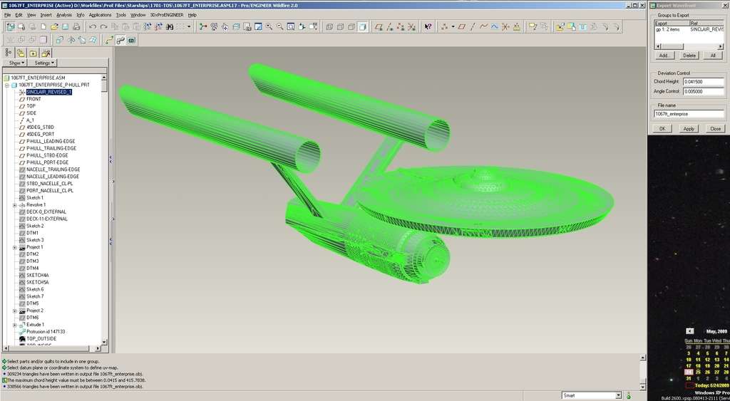
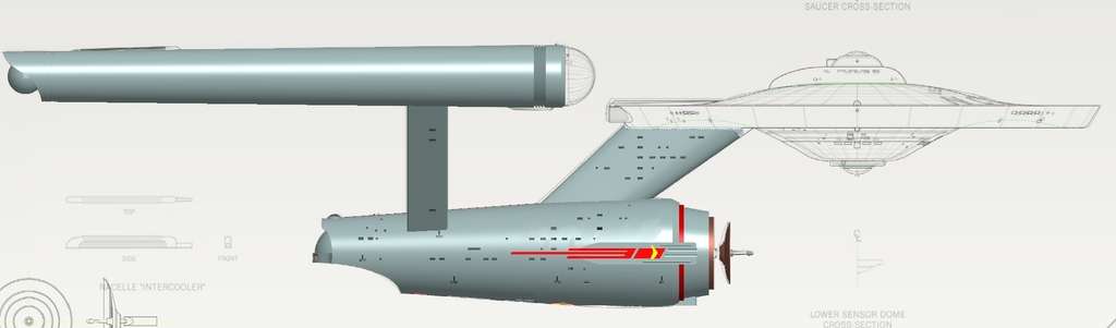
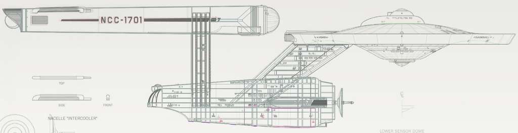
    Well, I finished off the exterior of the secondary hull tonight, and I've gotten a tiny bit more done inside of the nacelles (though I'm not yet ready to show off what I'm doing, as I'm still going back and forth on a few major issues and may delete some of what I've done).

    But, I did spend a little bit more time playing around with rendering, and (for my own use) created a few "wallpaper-friendly" images. Of course, this isn't finished, so I don't expect anyone will want to use them as such except me, but I thought I'd go ahead and share them anyway. These images are 1920x1080, so I'm providing them as thumbnails.

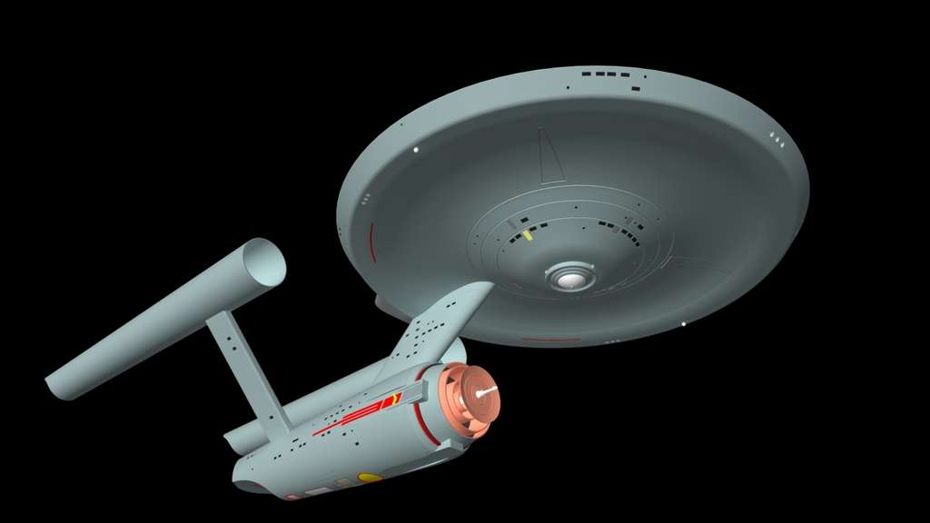
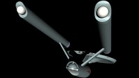
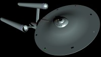
    I played around with focal lengths here. Most of the shots you see are shot with 12mm very-wide-angle lenses, with the exception of the last one, which I did with a standard 28mm lens (remember, my model is in 1:1 scale) so this looks like the "real" ship would look if shot with that sort of lens from this position.

    I wanted to go single-light-source, but the shadows were just TOO dark, and while I'd be inclined to do that if self-illumination were present, and/or if I were doing an animation (where the shadowed areas wouldn't be constant from frame to frame) in this case, I decided a minor "fill" light was still needed. In most cases, the main lights have an intensity of 9x the fill light, with the exception of the last image where the main light is 3x the fill. I think the results look pretty good, but realistically, there should be no fill light whatsoever except for in the final image.

    First, a replication of a couple of fairly common TOS shots:

    [​IMG] [​IMG]

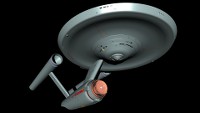
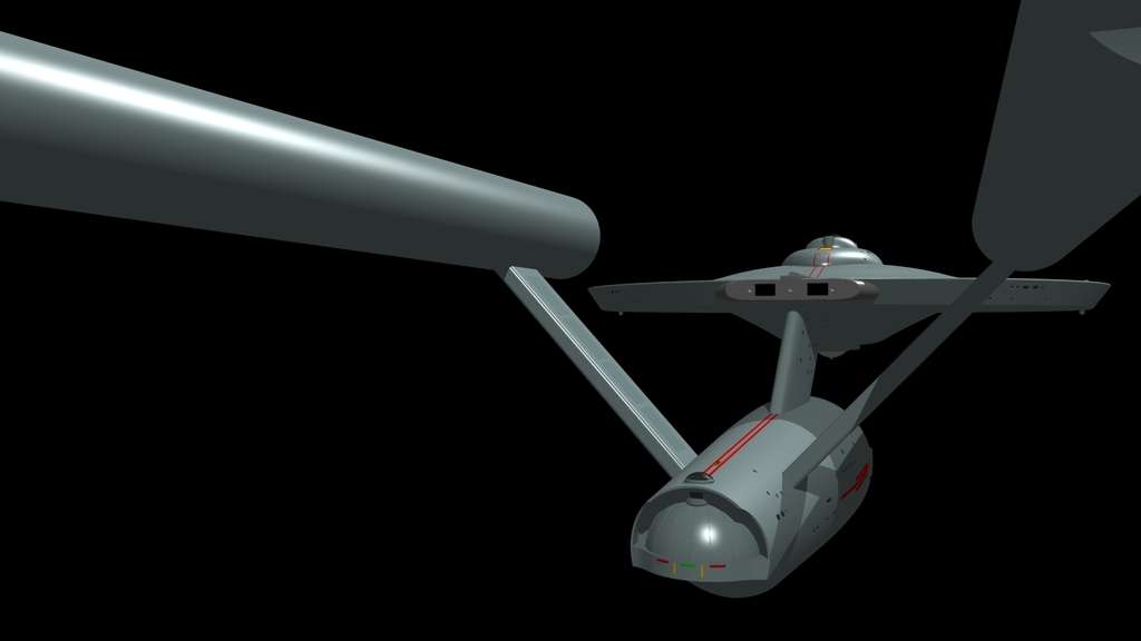
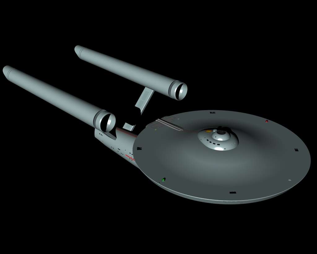
    Next, a couple of "dynamic" shots... the latter is a close representation of an image from a comic cover I remember from years ago, in fact... I thought that these made the best "wallpaper" compositions.

    [​IMG] [​IMG]

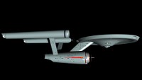
    Finally, the 28mm shot, with the extra fill light. This is a quick-and-dirty attempt to replicate what the ST-09 1st Trailer shot would have looked like had they used the "real" Enterprise.

    [​IMG]

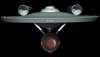
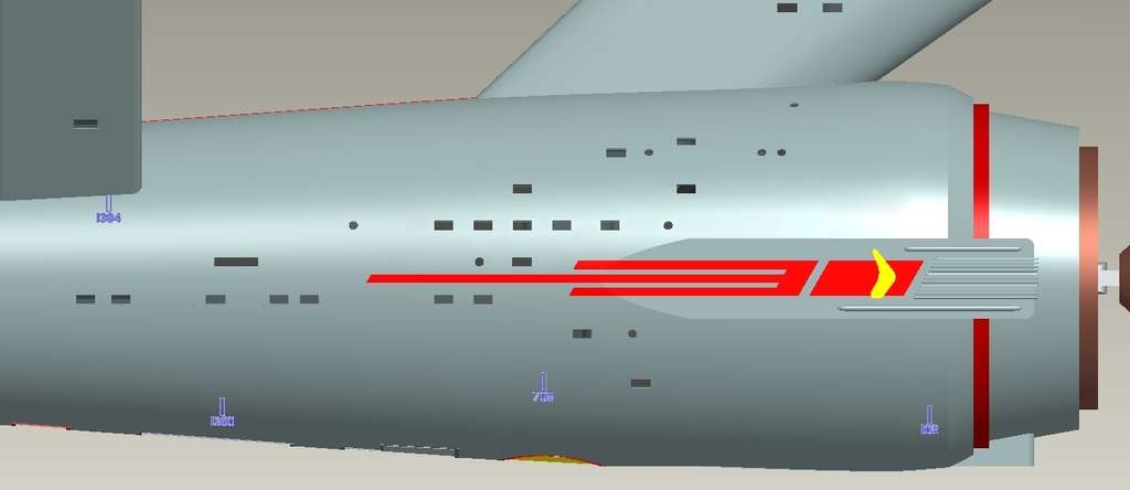
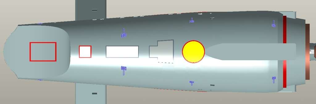
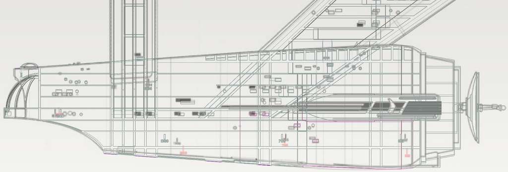
    You've probably noticed two color choices on the nacelles... one of which I am definitely going to change, the other which I'm very happy with.

    First, the angled rings behind the (as yet not present) dome... I colored them "blued steel" but they seem to be almost irridescent, which is unacceptable. Obviously, I'm going to have to change that.

    Second, the aft nacelle balls... which, in my case, are the actual warp field generation elements... I've colored a slightly off-white color intended to represent polished ceramic. They're not LIT, they're just lighter-colored... but they're definitely consistent with the TOS look. I've been thinking that if the ship is actually at warp, these might in fact produce some light. But few of the TOS shots showed these when the ship was at warp, so the trick is to keep things consistent with what was seen on-screen while still trying to make them make some sort of scientific/engineering/generally-logical sense. Having a super-hard ceramic coating over this device makes a great deal of sense to me... we do that all the time for our most "hardened" electronic components, after all.
     
Thread Status:
Not open for further replies.