I'm creating this area to be a place where topics can be discussed by any interested parties to greater depths. My reason for doing so are a number of comments that long posts are unwanted by some and potentially detrimental to the board's traffic. While the former is true, the latter I find in principle hard to believe, so this is my attempt at resolving such complaints.
Posts here may be very long, complex, and technical. If you're not interested in these kinds of posts, you aren't required to read them. While I intend to post in this thread, others are strongly encouraged to do so as well. We don't all have to agree but hopefully conversations will not get too heated. While it is 'rocket science' (of a sort), and at times it might be hard work, I hope we can still have some fun while we learn a thing or two about this "hobby".
Here are some earlier posts for reference:
http://www.trekbbs.com/showpost.php?p=2614152&postcount=96
http://www.trekbbs.com/showpost.php?p=2620604&postcount=112
http://www.trekbbs.com/showpost.php?p=2620624&postcount=113
Because we're having ice storms and freezing rain I may not be back on the board for several days to post, I'm releasing two parts of this three part study so that there is sufficient material to discuss over that span. Apologies for this particularly long post due to these circumstances.

Standard Articulation Study: Franz Joseph BoGP cross-section and Alan Sinclair's Revision D plans of TOS 1701
---Purpose
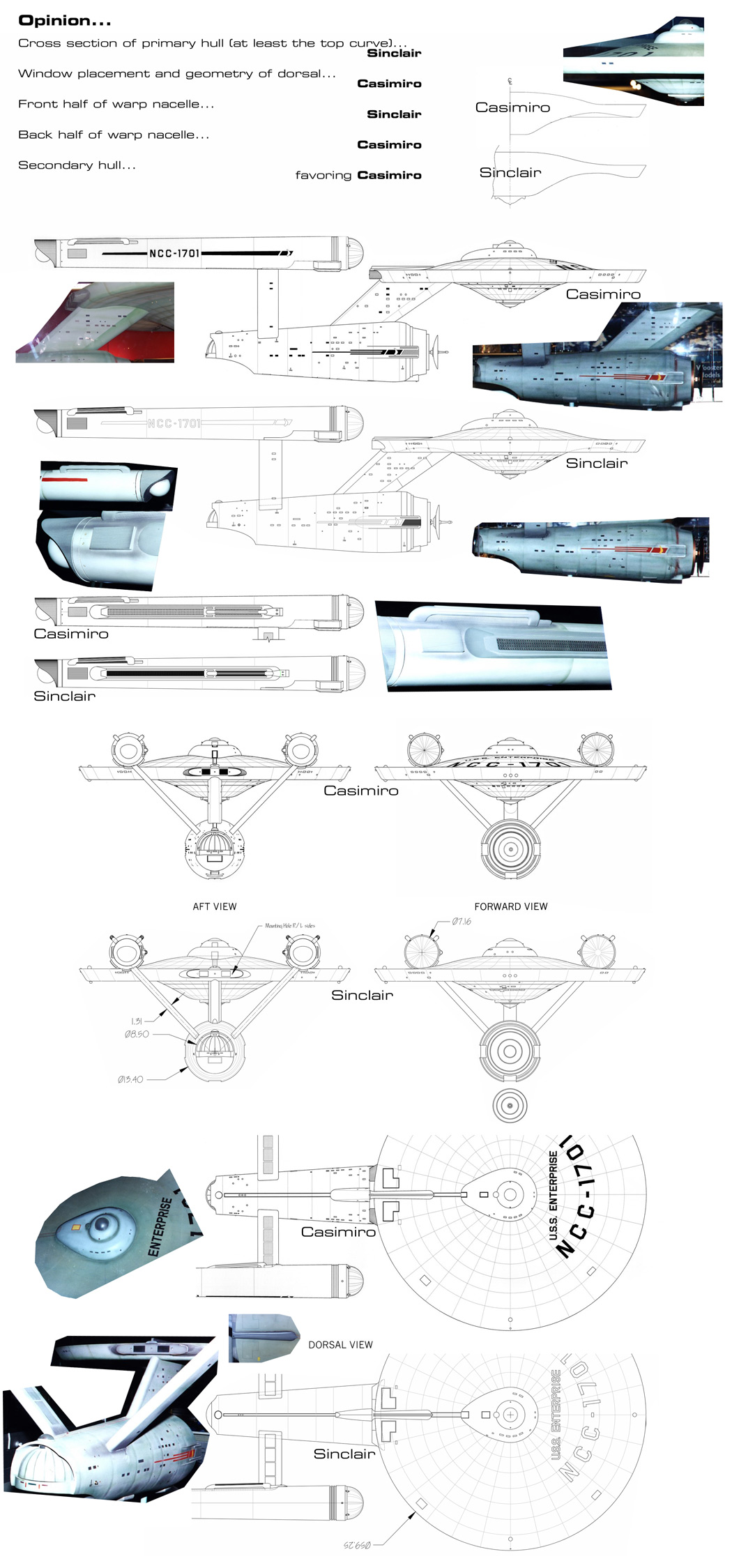
To compare the similarities and differences of the design found in the Franz Joseph (FJ) "Star Trek Booklet of General Plans" to the modern fan based plan reconstruction of Alan Sinclair (AS) on the basis of the entire configuration of each design.
--- Process: (the teach-a-man-to-fish section)
Cleaned up and properly oriented FJ cross-section (removed text, etc.).
Reconstructed unscanned areas of FJ upper/lower domes (as best as possible).
Selected background color.
Cleaned up Alan Sinclair port view (i.e., removed non-diagram components).
Resized overall length of ship to 2420 pixels to match the FJ diagram.
Changed Color Channel to full Red.
Selected background color.
Copied and pasted both as transparent images into a few file as separate layers.
Added a white background layer (for visibility).
Aligned primary hulls of two images, vertical centerline & upper/lower outer saucer decks (as best as possible).
--- Conclusions:
Are in the Conclusions section of the Rearticulated Study because either they are redundant or many/most rely on the rearticulation to make them clear.

Secondary Hull aligned forward.

Secondary Hull aligned aft.
Rearticulation Study: Franz Joseph BoGP cross-section and Alan Sinclair's Revision-D port-side diagram of TOS 1701
---Purpose:
To compare the similarities and differences of the design found in the Franz Joseph (FJ) "Star Trek Booklet of General Plans" to the modern fan based plan reconstruction of Alan Sinclair (AS). In this case, the large but separate components of the FJ design are repositioned on an individual basis to minimize global inaccuracies due to interfacing of parts and allow comparison on the 'modular' basis.
--- Process:
Continued on from the Standard Articulation Study procedures.
Replaced the AS outboard nacelle diagram with his alternate inboard diagram (that detail is now going to be of importance). Inboard port-view strut detail is not provided by AS so this was not added.
Separated the FJ Primary Hull, Interconnecting Dorsal, Secondary Hull, Nacelle Struts, and Warp Nacelles into separate layers.
AS diagram was placed as the top layer, ultimately.
Realigned the primary hull so that placement was optimized (fine tuning to maximize overall layout). It is possible that this is not absolutely correct, as comparing different features seemed to indicate small variations in suggested positioning. This might indicate scanning inaccuracies, drafting inaccuracies, printing inaccuracies, or interpretive errors on my part.
Realigned the interconnecting dorsal to match AS (the heavy outer lines make the fit quite plausible as is). After finishing the realignment of the secondary hull a notable gap between it and the interconnecting dorsal was found. There was no way around this without misaligning some other FJ component.
Realigned the secondary hull using the primary vertical turbolift shaft and the deflector dish shaft as reference points.
Moved FJ's pylons to align with AS plans (did not enlarge them).
Realigned FJ nacelle to AS, overlapping from the front. Cut & paste a small section of nacelle diagram that was overlapping the strut diagram and repasted it to fill the gap created by repositioning the nacelle.
--- Conclusions:
As expected, FJ's plans were sometimes similar to but often out of conformity with the AS plans. As we believe that AS's plans are more accurate to the original 11' studio model, what is the nature of the inconsistencies. They fall into two types: structural inaccuracies (how things are shaped, and their relative size) and articulation (how the various parts are positioned together as individual modules).
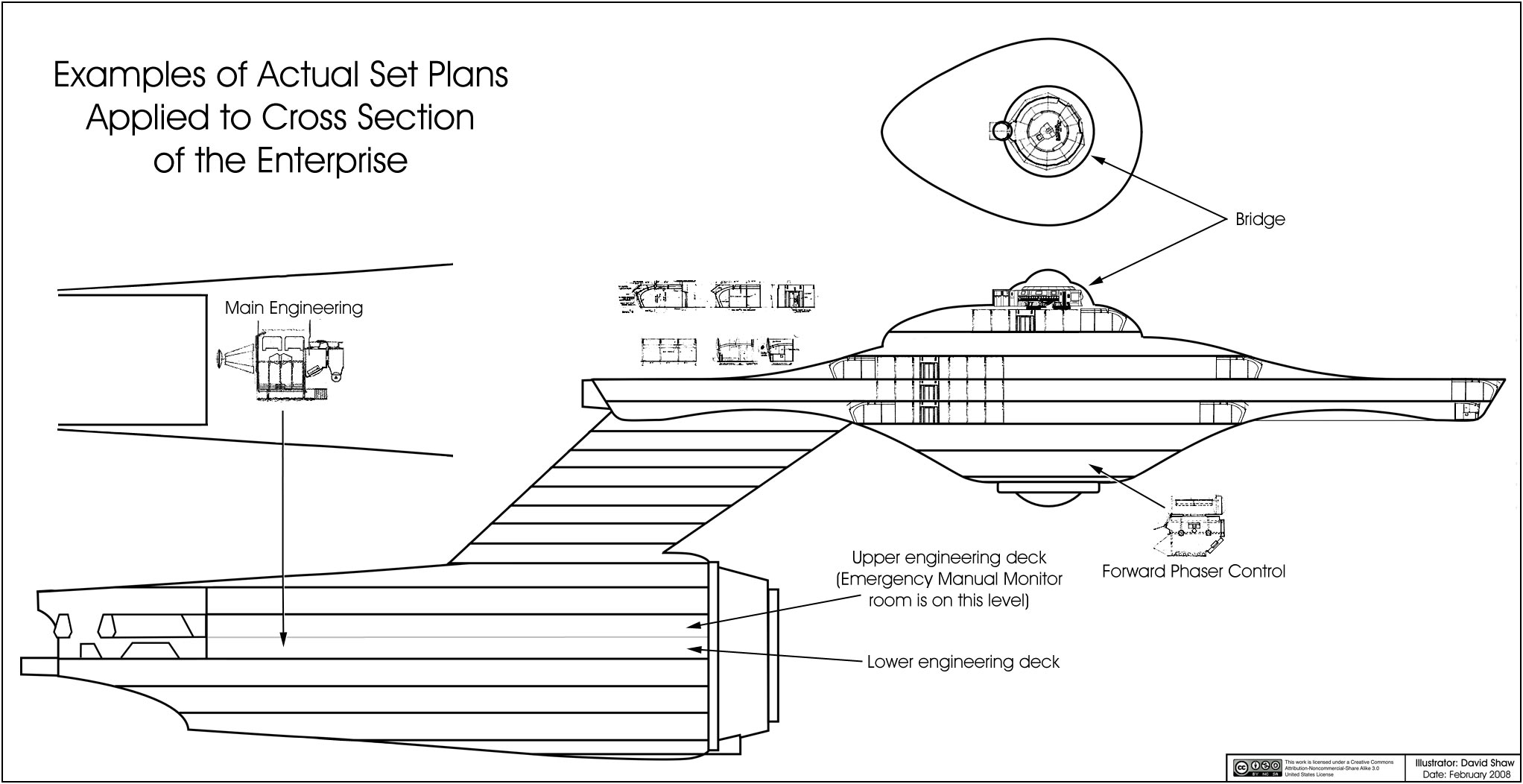
Overall height of the primary hull is similar and FJ's deck spacing seems highly plausible in comparison to AS external diagram, with the Bridge, FJ Deck 2, and Deck 11 possibly having minor issues. FJ's Bridge deck needs to be sunk slightly (perhaps a couple feet) to conform with the height of the underlying 'command pod' in AS's plans, but this would bring all vertical elements of FJ's Bridge plans into close alignment with AS. FJ's 'command pod' is more forward set, but otherwise appears very similar, though somewhat lower than height. Moving this component aft somewhat would offset a number of differences, but would require repositioning the turbolift shaft in that section of any plans. Some differences will probably remain. FJ's bridge and turbolift shaft are perhaps 20% larger in all dimensions. FJ's upper sensor dome is much larger than AS, and this may have to do somehow with production changes in this part of the 11' model, as it seems out of proportion. Contours of portions of the upper and lower inner primary hull do not match. FJ has more volume in the lower primary hull (FJ Decks 7-10, with upper decks being the most different), AS has slightly less in the upper primary hull (primarily FJ Deck 4). AS has the primary hull undercut (the continuation of the lower hull contour) significantly more pronounced than FJ, and this would impact the midsection of Deck 7 particularly. FJ's impulse housing is somewhat shorter, slightly lower on top, and undercut at the lower aft section compared to AS.
FJ's interconnecting dorsal is somewhat narrower and more rearward set than AS. FJ's secondary hull is shorter than AS, causing the forward sections and the deflector dish to be misaligned in the "standard articulation" diagram. The rear of the hanger fantails are aligned, but FJ's hanger area does not extend upward enough to match AS's dorsal backbone until repositioned, and the FJ sub-hanger deck area and adjacent areas are particularly smaller than AS. The lower keel of both diagrams almost align without repositioning, with FJ extending slightly lower than AS. After repositioning to align the forward part of the secondary hull in the two diagrams, the shortness of FJ's secondary hull becomes apparent, and the hanger area appears to be far too small, not to mention short, the aft part (and perhaps sides) of Deck 24 are eliminated, and the unnamed area of hull below it disappears completely. Realigning to match the overhang of the hanger bay cowling makes more of Deck 24 disappear and misaligns the primary vertical turbolift shaft, but removes most of the inconsistencies with AS in regard to the aft secondary hull, while generating enormous ones at the front. Ultimately I decided to match the forward section alignment as this seemed to cause the least serious overall alignment issues and made revising plans somewhat less of a nightmare as a prospect. Approximately half a deck is lost in the unnamed, unnumbered, outer hull section below Deck 24 and approximately that distance is gained with the new gap where the secondary hull attaches to the interconnecting dorsal.
From this perspective FJ's nacelle struts are narrower and somewhat too far forward, comparison of inboard detail is lacking from this particular angle in AS's plans so they are not compared here. The warp nacelles are set higher in relation to the rest of the ship in FJ's plans, and not far enough forward in comparison to AS. Major nacelle components tend to be close, but not precisely aligned, with accuracy tending to decrease the further aft we go. The forward part of the nacelles is in almost perfect agreement, with the exception that FJ's "Pre-Stage Flux Tuners" (the three forward rectangles) are slightly longer, narrower, and significantly thicker, as well as being positioned somewhat differently than AS. The inboard nacelle "Flux Stage" (inner panel) detailing matches in certain aspects, but not closely, between the plans. FJ's "Space Matrix Restoration Balancers" (the rectangles at the rear) are considerably longer than AS but otherwise correspond well. FJ's aft "Intercoolers" are almost identically attached, but are taller or at a different angle, with some detail differences. FJ's "Matrix Tuning Cowl" is shorter than AS and the "Space Matrix Restoration Coil" (aft sphere) is more deeply inset in FJ's plans.
--- Footnote
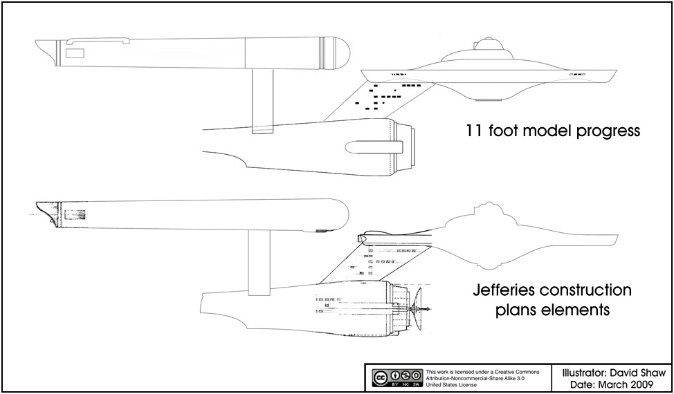
Why is this study so much shorter than my previous Dave Shaw to FJ comparison? In that study we were manipulating two different views of the internal layout of the ship as well as external layouts, and creating a hybrid as a hypothetical model. Here, we are taking FJ's decks "as given", and primarily comparing the external hull outlines. A study could be taken to compare the externalities of FJ's design to AS (et al.) but primarily this would indicate cosmetic issues rather than underlying structural deficits. Our next step in this study will examine the ramifications of the Alan Sinclair configuration on deck layout using FJ's design as a hypothetical model.
Posts here may be very long, complex, and technical. If you're not interested in these kinds of posts, you aren't required to read them. While I intend to post in this thread, others are strongly encouraged to do so as well. We don't all have to agree but hopefully conversations will not get too heated. While it is 'rocket science' (of a sort), and at times it might be hard work, I hope we can still have some fun while we learn a thing or two about this "hobby".
____________
Here are some earlier posts for reference:
http://www.trekbbs.com/showpost.php?p=2614152&postcount=96
http://www.trekbbs.com/showpost.php?p=2620604&postcount=112
http://www.trekbbs.com/showpost.php?p=2620624&postcount=113
____________
Because we're having ice storms and freezing rain I may not be back on the board for several days to post, I'm releasing two parts of this three part study so that there is sufficient material to discuss over that span. Apologies for this particularly long post due to these circumstances.
____________

Standard Articulation Study: Franz Joseph BoGP cross-section and Alan Sinclair's Revision D plans of TOS 1701
---Purpose
To compare the similarities and differences of the design found in the Franz Joseph (FJ) "Star Trek Booklet of General Plans" to the modern fan based plan reconstruction of Alan Sinclair (AS) on the basis of the entire configuration of each design.
--- Process: (the teach-a-man-to-fish section)
Cleaned up and properly oriented FJ cross-section (removed text, etc.).
Reconstructed unscanned areas of FJ upper/lower domes (as best as possible).
Selected background color.
Cleaned up Alan Sinclair port view (i.e., removed non-diagram components).
Resized overall length of ship to 2420 pixels to match the FJ diagram.
Changed Color Channel to full Red.
Selected background color.
Copied and pasted both as transparent images into a few file as separate layers.
Added a white background layer (for visibility).
Aligned primary hulls of two images, vertical centerline & upper/lower outer saucer decks (as best as possible).
--- Conclusions:
Are in the Conclusions section of the Rearticulated Study because either they are redundant or many/most rely on the rearticulation to make them clear.
____________

Secondary Hull aligned forward.

Secondary Hull aligned aft.
Rearticulation Study: Franz Joseph BoGP cross-section and Alan Sinclair's Revision-D port-side diagram of TOS 1701
---Purpose:
To compare the similarities and differences of the design found in the Franz Joseph (FJ) "Star Trek Booklet of General Plans" to the modern fan based plan reconstruction of Alan Sinclair (AS). In this case, the large but separate components of the FJ design are repositioned on an individual basis to minimize global inaccuracies due to interfacing of parts and allow comparison on the 'modular' basis.
--- Process:
Continued on from the Standard Articulation Study procedures.
Replaced the AS outboard nacelle diagram with his alternate inboard diagram (that detail is now going to be of importance). Inboard port-view strut detail is not provided by AS so this was not added.
Separated the FJ Primary Hull, Interconnecting Dorsal, Secondary Hull, Nacelle Struts, and Warp Nacelles into separate layers.
AS diagram was placed as the top layer, ultimately.
Realigned the primary hull so that placement was optimized (fine tuning to maximize overall layout). It is possible that this is not absolutely correct, as comparing different features seemed to indicate small variations in suggested positioning. This might indicate scanning inaccuracies, drafting inaccuracies, printing inaccuracies, or interpretive errors on my part.
Realigned the interconnecting dorsal to match AS (the heavy outer lines make the fit quite plausible as is). After finishing the realignment of the secondary hull a notable gap between it and the interconnecting dorsal was found. There was no way around this without misaligning some other FJ component.
Realigned the secondary hull using the primary vertical turbolift shaft and the deflector dish shaft as reference points.
Moved FJ's pylons to align with AS plans (did not enlarge them).
Realigned FJ nacelle to AS, overlapping from the front. Cut & paste a small section of nacelle diagram that was overlapping the strut diagram and repasted it to fill the gap created by repositioning the nacelle.
--- Conclusions:
As expected, FJ's plans were sometimes similar to but often out of conformity with the AS plans. As we believe that AS's plans are more accurate to the original 11' studio model, what is the nature of the inconsistencies. They fall into two types: structural inaccuracies (how things are shaped, and their relative size) and articulation (how the various parts are positioned together as individual modules).
Overall height of the primary hull is similar and FJ's deck spacing seems highly plausible in comparison to AS external diagram, with the Bridge, FJ Deck 2, and Deck 11 possibly having minor issues. FJ's Bridge deck needs to be sunk slightly (perhaps a couple feet) to conform with the height of the underlying 'command pod' in AS's plans, but this would bring all vertical elements of FJ's Bridge plans into close alignment with AS. FJ's 'command pod' is more forward set, but otherwise appears very similar, though somewhat lower than height. Moving this component aft somewhat would offset a number of differences, but would require repositioning the turbolift shaft in that section of any plans. Some differences will probably remain. FJ's bridge and turbolift shaft are perhaps 20% larger in all dimensions. FJ's upper sensor dome is much larger than AS, and this may have to do somehow with production changes in this part of the 11' model, as it seems out of proportion. Contours of portions of the upper and lower inner primary hull do not match. FJ has more volume in the lower primary hull (FJ Decks 7-10, with upper decks being the most different), AS has slightly less in the upper primary hull (primarily FJ Deck 4). AS has the primary hull undercut (the continuation of the lower hull contour) significantly more pronounced than FJ, and this would impact the midsection of Deck 7 particularly. FJ's impulse housing is somewhat shorter, slightly lower on top, and undercut at the lower aft section compared to AS.
FJ's interconnecting dorsal is somewhat narrower and more rearward set than AS. FJ's secondary hull is shorter than AS, causing the forward sections and the deflector dish to be misaligned in the "standard articulation" diagram. The rear of the hanger fantails are aligned, but FJ's hanger area does not extend upward enough to match AS's dorsal backbone until repositioned, and the FJ sub-hanger deck area and adjacent areas are particularly smaller than AS. The lower keel of both diagrams almost align without repositioning, with FJ extending slightly lower than AS. After repositioning to align the forward part of the secondary hull in the two diagrams, the shortness of FJ's secondary hull becomes apparent, and the hanger area appears to be far too small, not to mention short, the aft part (and perhaps sides) of Deck 24 are eliminated, and the unnamed area of hull below it disappears completely. Realigning to match the overhang of the hanger bay cowling makes more of Deck 24 disappear and misaligns the primary vertical turbolift shaft, but removes most of the inconsistencies with AS in regard to the aft secondary hull, while generating enormous ones at the front. Ultimately I decided to match the forward section alignment as this seemed to cause the least serious overall alignment issues and made revising plans somewhat less of a nightmare as a prospect. Approximately half a deck is lost in the unnamed, unnumbered, outer hull section below Deck 24 and approximately that distance is gained with the new gap where the secondary hull attaches to the interconnecting dorsal.
From this perspective FJ's nacelle struts are narrower and somewhat too far forward, comparison of inboard detail is lacking from this particular angle in AS's plans so they are not compared here. The warp nacelles are set higher in relation to the rest of the ship in FJ's plans, and not far enough forward in comparison to AS. Major nacelle components tend to be close, but not precisely aligned, with accuracy tending to decrease the further aft we go. The forward part of the nacelles is in almost perfect agreement, with the exception that FJ's "Pre-Stage Flux Tuners" (the three forward rectangles) are slightly longer, narrower, and significantly thicker, as well as being positioned somewhat differently than AS. The inboard nacelle "Flux Stage" (inner panel) detailing matches in certain aspects, but not closely, between the plans. FJ's "Space Matrix Restoration Balancers" (the rectangles at the rear) are considerably longer than AS but otherwise correspond well. FJ's aft "Intercoolers" are almost identically attached, but are taller or at a different angle, with some detail differences. FJ's "Matrix Tuning Cowl" is shorter than AS and the "Space Matrix Restoration Coil" (aft sphere) is more deeply inset in FJ's plans.
--- Footnote
Why is this study so much shorter than my previous Dave Shaw to FJ comparison? In that study we were manipulating two different views of the internal layout of the ship as well as external layouts, and creating a hybrid as a hypothetical model. Here, we are taking FJ's decks "as given", and primarily comparing the external hull outlines. A study could be taken to compare the externalities of FJ's design to AS (et al.) but primarily this would indicate cosmetic issues rather than underlying structural deficits. Our next step in this study will examine the ramifications of the Alan Sinclair configuration on deck layout using FJ's design as a hypothetical model.


")

")