Another fan attempt at TOS deck plans

Discussion in 'Fan Art' started by Shaw, Feb 11, 2008.

Thread Status:
Not open for further replies.
  1. Shaw

    Shaw Commodore Commodore

    Joined:
    Feb 21, 2007
    Location:
    Twin Cities
    So I was considering the dorsal... which I think is a greatly under utilized area in fan based plans. In my current sketches the dorsal has 8 levels which are about 17 feet wide and 120 feet long. Assuming that the front and back areas are devoted to interconnection tasks, that still leaves a lot of room. So when you think about it, that seems like a great place to put offices and the like... and most would seem to have windows based on the model.

    Additionally, I couldn't come up with a good reason why the turbolift should run down the center of the dorsal. Moving it off to one side would seem like a better use of space.

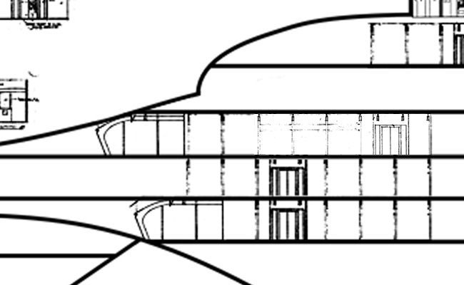
    In this image I've included a number of set elements and some example layouts to help illustrate the general size of the area we are talking about. Other than the placement of the turbolift tubes, I'm not planning on populating these deck levels in a final version as we never actually saw them (that I know of). I just thought that playing with the utility of these decks would be interesting.

    The shape of the decks is based on the dorsal from my 33 inch Enterprise plans. I haven't spent enough time on studying the 11 foot model's dorsal to have my own drawings of it as yet.
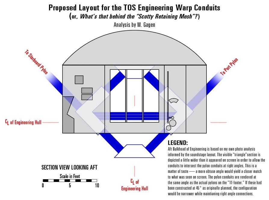
     
  2. MGagen

    MGagen Fleet Captain Fleet Captain

    Joined:
    Feb 28, 2003
    Location:
    Crucis Court, Trans-Coal Sack Sector
    Then again, maybe not...

    [​IMG]
    Click to Enlarge


    This is a drawing I did several years ago to show how the conduits behind the "Scotty Retaining Mesh" could actually link up with the pylons. It posits that we are seeing only part of the structure. If you were to walk up to the mesh and look down, you would see that rather than a triangle, it is actually a diamond structure extending below main Engineering deck level. An additional tube would run from the lower junction forward under the floor and link up with that dilithium thingie in the middle of the deck. (I don't know what it's called or what it's supposed to be doing. I am not a warp engineer, nor do I play one on TV...)

    This solution has the benefit of situating Engineering in precisely the same location that Jefferies calls out for it in the Phase II plans: Immediately forward of the pylons with a deck level 2 feet below the hull center line.

    Just food for thought. Of course, YMMV.

    M.
     
  3. Shaw

    Shaw Commodore Commodore

    Joined:
    Feb 21, 2007
    Location:
    Twin Cities
    Originally I was going off of the assumption that your diagram was correct, but when double checking to see if your wall elements lined up correctly (which they do quite nicely :thumbsup: ), what I found was that the tubes weren't at the correct angles.

    [​IMG]

    You could still argue that the configuration works even without them being at 45 degrees. But if the original argument for the configuration was based on them being at 45 degrees, then the strength of the configuration argument becomes weaker if they aren't.

    So for these plans there just isn't enough information to make assumptions of connecting... well, anything. So I'll be skipping that type of stuff all together.

    Now if I was trying to envision how it might work, then I could justify changing the angles because I liked your argument for the connections. I'm just not willing to make those types of editorial modifications for this project. The absents of information will be represented by an absents of detail for this project.
     
  4. Harry

    Harry Captain Captain

    Joined:
    Feb 29, 2000
    That's a quite a cool approach (and gives a nice 'basic' template from which other people could perhaps try to fill it in).

    But it does indeed some logical that the 'thing' behind the grill is somehow connected to the warp engines, though not necessarily as directly as Mgagen's schematic.
     
  5. Shaw

    Shaw Commodore Commodore

    Joined:
    Feb 21, 2007
    Location:
    Twin Cities
    When looking at warp design what I see are two schools of thought that are not that unlike some naval propulsion designs. Specifically, the two that I'm thinking of are nuclear/steam turbine and nuclear/turbo-electric.

    The nuclear/steam turbine idea is more like what was shown in TMP and later. This uses two enclosed water/steam systems, the first being with the reactor like a standard nuclear reactor core. The second passes beside the first, with no exchange of water, but with a transference of heat. This second system powers the main propulsion.

    The nuclear/turbo-electric idea is actually more like the evidence shown in TOS, where the nuclear reactor generates electricity which is then used to power turbo-electric engines. These engines, being electrically powered, could also run off of battery power if needed.

    Eventually the US Navy went with the nuclear/steam turbine design for almost all of it's nuclear vessels. The handful of nuclear/turbo-electric examples (a couple of submarines used this) were far quieter, but also weighed quite a bit more.

    Actually, if I was going to point to a propulsion system that best matches what we saw in TOS, it would be a diesel/turbo-electric system similar to pre-nuclear submarines. The main propulsion is two turbo-electric engines, but the electrical power is generated by four diesel generators (which were able to breath via a snorkel at shallow depths), and stored in some 500 battery cells.

    Of course TOS was a weekly television show, and drama was far more important than ideal functionality. I think that with the designs seen in later shows and fans trying to come up with the best solution rather than the solution that would provide the most drama has lead to a lot of the over thinking of this subject. Sure, basing the TOS Enterprise design on later incarnations of warp theory is convenient, but it also leads to people yelling at the screen because of perceived inconsistencies.

    So basically, what I'm doing here is divorcing these plans from all post-TOS ideas, looking at what stuff does which things (the black box idea), and where they all might be situated. The hows and whys are left to the readers imagination... and that could include rearranging stuff to make a warp system that is more like post-TOS if they want.
     
  6. felixofgolden

    felixofgolden Lieutenant Commander Red Shirt

    Joined:
    Apr 30, 2007
    I don't get it.
    You're making a detailed criticism of this fellow's ideas, but when someone does it for yours - heck it wasn't even criticisms of your ideas, just clarifications of technical information (layout of a room as seen on screen with description of positioning and directions, or proper spelling of a word as to add accuracy to your project, whatever that is, other than to drop in rooms onto a deck with the rest blank), you respond by saying don't push me, why do I bother posting on here when people just point out flaws and so on.
    Isn't that the reason for posting on here, is to get input? You can't pick and choose what input that is, not just the ones that say "great job keep it up".
    Maybe I'm missing something.
     
    Last edited: Mar 6, 2008
  7. Shaw

    Shaw Commodore Commodore

    Joined:
    Feb 21, 2007
    Location:
    Twin Cities
    Just a few things...

    First, I was explaining why that part of MGagen's work extends just beyond the level of theorizing that I want to apply to these plans. But I would hardly call it a criticism as I was referencing his work in this area pretty much from the start. Plus I pointed out that if I wasn't going to follow the restrictions I've put on myself for this project, I would most likely go with his idea as I've always liked it. Sounds more like an endorsement than a criticism to me.

    Second, people have been putting forward criticisms from the beginning of the thread, some are about details that are beyond the stated scope of these plans, others I either argued against or made changes based on them. It is a long thread, but to think that it has been without critical comments towards my work seems a little odd.

    Lastly, as stated a number of posts earlier, my indignation towards B.J. was supposed to be a joke, but as April pointed out, a lack of smileys meant that the tone was lost and the meaning mistaken. If I had meant anything that I said, why in the world would I still be posting updates?

    But no one is forcing anyone to follow this thread, so if you don't care for either me or my workmanship, please don't feel compelled to participate.

    I'm only human, and if you can't accept my strengths and weaknesses, there really isn't much I can do to help you with that. I'm too old to change now. :eek:


    Edit:
    That was pretty much pointed out from the beginning of thread... I am not going to address the actual room layouts (cleaning up and the like) until I have the time. When will I have the time? On page 1 of this thread I said it would most likely be around April. Correcting Matt Jefferies work isn't what I was planning on doing at this point. I've tried to let people know that this stuff is raw, and not meant as anything close to final work. We are looking at the digital equivalent of cocktail napkin drawings. Nothing you've seen so far will be in the final project... everything for that will be redrawn from scratch.

    I would hope that I wouldn't have to clarify this every few post throughout this thread, but maybe it would help people keep this in mind. :brickwall:
     
    Last edited: Mar 6, 2008
  8. Shaw

    Shaw Commodore Commodore

    Joined:
    Feb 21, 2007
    Location:
    Twin Cities
    Announcement:
    It has come to my attention (over and over again) that people are missing the point of what I'm posting here. So to clarify, here are a few things to keep in mind...
    1. This is the very beginning of a long project which includes both a generalize set of floor plans of the Enterprise, and a cleaned up version of the set plans from TOS. Don't expect the final product until the end of summer (at the earliest). Corrections to Jefferies' set plans will not start any time before April (and most likely not until May). Anyone feeling the urge to make corrections on their own are encouraged to post their efforts, but don't expect me to take any time for that type of stuff until I have time for that type of stuff.
    2. Nothing posted in this thread is going to be in the final project. All the artwork posted to date, and all of the artwork that will be posted over the coming months is nothing more than scratch work. Even if you think it looks good enough to be the final product, IT ISN'T! These are just sketches of ideas done super fast and dirty, and so if you think the quality is awesome or sucks, it doesn't matter, they only exist to discuss what we are talking about and nothing more. While I find it humorous to see people correcting the spelling on what is nothing more than a digital version of a cocktail napkin drawing, it really is a waste of effort as none of this is heading towards the final project anyways.
    3. I am not going to invent, reinvent or discover 23rd century technology in this project. I'm not going to attempt to invent, reinvent or discover fictional 23rd century technology in this project. I am only documenting what was seen on screen using the original plans for what was seen on screen and very little above and beyond that. As such, much of these plans will be blank when finished. While I find most people's concepts of what might be going on in unseen areas of the ship quite interesting, if we didn't actually see it (or something like it) on screen, odds are it wouldn't make it into these plans.
    Now, I know I've stated all this before, but it seems as though I need to restate this every couple days or so as someone invariably forgets or hasn't been following the thread.

    So if you are aware of the above (and I know a lot of you guys are), please ignore these posts where I restate the purpose of what is happening here.

    Thanks.
     
  9. felixofgolden

    felixofgolden Lieutenant Commander Red Shirt

    Joined:
    Apr 30, 2007
    Ah.. April's smiley reference was to your post? He just said smiley's are helpful. Maybe that was reference to some other post in the thread, since BJ's answer was as mine is, confusion as to why you're critical of helpful notes being given - notes which don't refer to any work you've done yourself. Apologies for that, I thought your response to BJ was a serious one, it sure sounded like it was. I don't know why you would stop or continue to post updates if that BJ bugaboo was real, I can't read your mind.

    Just seemed like a long thread discussing things when it appears that you're just positioning a few rooms with nothing around them - yes I know, it will come later, and hence helpful suggestions and clarification of source information such as stage plans and the like are taken as too much detail. My mistake there. I guess I didn't realize it was in *that* raw a state.

    It's your reaction to comments that I found odd. Saying "but to think that it (the thread) has been without critical comments towards my work seems a little odd", is incorrect. I never said they never existed in the thread. They obviously do. Don't put words into my mouth.

    I also never criticized your ideas, strengths, weaknesses, nor workmanship, only found your reaction to technical clarification strange.
    Ok, I guess that can be a weakness, so ok, I criticized a weakness. It wasn't intended to be that though, which is why I asked what I was missing. Again, don't put words into my mouth, and imply I'm attacking your workmanship or ideas. I've never done that. I've pointed out errors in stage plans drawn up 40 years ago, and expressed confusion as to why you get so defensive when people give useful input that have nothing to do with your own ideas and work.
    If "Nothing you've seen so far will be in the final project... everything for that will be redrawn from scratch" is supposed to mean that I expected that stage plans beside a cross section was to be some sort of final version of things, again, I've never said anything about the quality of those images.
    I'm sure your workmanship will be just fine when it is shown.

    "But no one is forcing anyone to follow this thread, so if you don't care for either me or my workmanship, please don't feel compelled to participate." - I've never said I didn't care for you (I don't know you), or your work (haven't seen much of it, and have never criticized it - have I mentioned that yet?), so I'll continue to follow whatever threads I desire.

    Thanks for the clarification of my misinformationial misunderstandings on the state on the project.
    Is that everything, Harvey?, yeah, that's everything.
    Stop banging your head against the wall too, you'll hurt yourself. :brickwall:;)
     
    Last edited: Mar 6, 2008
  10. Shaw

    Shaw Commodore Commodore

    Joined:
    Feb 21, 2007
    Location:
    Twin Cities
    Maybe I'm missing something here... if all you see is the positioning of a few rooms, why in the world are you reading and (more to the point) posting in this thread? It seems that I have nothing to offer that would be of any interest to you, so why waste your time here? Seems rather odd. :wtf:

    What has always been a major hurdle in doing this type of stuff has been scaling, so while my moving some rooms around may be beneath you, the fact that (even in these rough sketches) everything is being scaled correctly should (I hope) be helpful to other people.

    And it should be noted that I'm not asking for praise, nor is that the point of this work. I share my work in the hope that it'll be helpful to others.

    Now, obviously this project (which in your mind seems to be just positioning a few rooms with nothing around them) has no possible value to you, so maybe you'll do the rest of us a favor and find a thread you can both contribute to and get something from. It is painfully clear that this just isn't the thread for you (as you seem intent on staying about as far off topic as you can get).

    Of course you could post that drawing of the corrected forward phaser control room that you were going to provide us... that would be a great way to get back on topic. Otherwise, let the rest of us get back to the topic of the thread (which isn't you).
     
  11. felixofgolden

    felixofgolden Lieutenant Commander Red Shirt

    Joined:
    Apr 30, 2007
    Wow, don't tell me what threads to read and what not to read - that's not your decision nor choice, or to give orders to post drawings. Or say I'm not interested in the thread. I am, that's why I have talked about the ion pod, the phaser room, etc. Have a nice day.
    :)
     
  12. Shaw

    Shaw Commodore Commodore

    Joined:
    Feb 21, 2007
    Location:
    Twin Cities
    Now don't start putting words into my mouth.

    But I do recall there being some rules here for keeping threads on topic... do you have anything topical to add?
     
  13. felixofgolden

    felixofgolden Lieutenant Commander Red Shirt

    Joined:
    Apr 30, 2007
    Good point, it's gotten way off topic, and you didn't specifically order anything, only asked. It just felt like ordering because things were getting out of hand.

    If it's not too much detail (that's not sarcasm), I was wondering if you've had any thoughts about how to put the full corridor height into the cross sections. Those plastic panels above the corridors never seem to fit into a cross section of a corridor (making very tall corridors) and still have reasonable number of decks in the ship.
     
    Last edited: Mar 6, 2008
  14. Shaw

    Shaw Commodore Commodore

    Joined:
    Feb 21, 2007
    Location:
    Twin Cities
    That was always one of those things that I thought was an error on the part of the art department on the show... the deck heights in FJ were far lower than those seen on screen, and I thought FJ knew better or that the art department hadn't worked it out (sorta like the three decks of the Jupiter 2). Then last summer while cleaning up some Phase II Enterprise plans I realized that the drawing by Jefferies for the writers guide wasn't a mistakenly drawn diagram, but (for it's size) was actually what he had in mind. So that was when I adopted the 10 foot deck height as the actual height rather than an oversight of the production team.

    This is a closer version (with a clearer view of a corridor section) showing how they can fit even with the hanging panels.

    [​IMG]

    So part of this is curiosity to see if everything actually fits with the taller decks. I'm starting to think that because Jefferies had nearly two years to think about this before the series started regular production that he may have really thought this through.
     
  15. aridas sofia

    aridas sofia Rear Admiral Rear Admiral

    Joined:
    May 3, 2002
    That's been my main point for oh... six years and 4,000 posts.
     
  16. Shaw

    Shaw Commodore Commodore

    Joined:
    Feb 21, 2007
    Location:
    Twin Cities
    Yes, I know... it isn't an original idea. And I admit that the very first time I saw your cross section over at the Exeter forums the first question I had was "why so few decks?"

    But I got one of FJ's first prints of his blueprints in the first grade, carried them around (along with the technical manual) just about every where I went until about 1982... that is a lot of early indoctrination to over come. :eek:

    And I have to admit, it has taken quite some time to get to a place where I can set aside both FJ's work and all post-TOS Trek, and just look at TOS on it's own.

    And just like when I look at the work of Sinclair and Casimiro, when I look at your progress I have to wonder if I actually have anything useful to contribute. I hope so, and really want to make something that other people can use. But I hate reinventing the wheel... or worse, climbing a mountain to find someone else already at the top eating their lunch.

    That was why it was so much easier to spend time on the 33 inch or Phase II Enterprise plans... those were unclimbed mountains. In the case of the 11 foot Enterprise and Enterprise deck plans, the best I can hope for is to find a new route to the top (and I can already see that you've taken at least part of this route... oh look, you ate lunch right over there! :drool: ).
     
  17. MGagen

    MGagen Fleet Captain Fleet Captain

    Joined:
    Feb 28, 2003
    Location:
    Crucis Court, Trans-Coal Sack Sector
    Not to derail your thread into a side discussion, but I'd like to point out a couple of things about my proposal that I think you may have missed. In the end, it's your project, of course. And I'm not making the case that this solution is either canon, or definitely what MJ intended -- it's just an interesting possibility. To wit:

    The legend on my drawing indicates that the intersection of the conduits at 90 degrees was a "matter of taste" and that I had depicted the structure wider than shown on the set to accomplish this. My proposal wasn't "based on" these junctions being 90 degrees, and so I don't see this as necessarily a deal breaker. In fact, my proposal is based on Jefferies' explicit direction about the location of engineering on his Phase II plans. A location that works very well with the conduits linking up with the pylons somehow.

    But, more to the point: does my drawing really not match the set? Let's take a look at your convenient and workman-like application of my drawing to the set photo:

    [​IMG]

    Notice that one of the odd features of the set itself is that the conduits are not all at the same angle. This is part of what I take to be the forced perspective built into the piece. Now every forced perspective design has an optimal viewpoint it is designed for. I think it is pretty obvious that the optimal viewpoint for this set is lower than eye level (like the image), but closer to the grille than this image. The foreground conduits are intended to give the impression that they are taller than they actually are and that you are looking up in to the space behind the grille. Now take a look at the last set of conduits. These are the ones that would be the most distant, and in any perspective scheme (real or forced) would appear closer to their true angle. The further you are from an object, the less the distortion caused by your viewpoint becomes a factor and the closer to a flat, orthographic view you get. So, what "true" angle is suggested by the last set of conduits? It looks pretty close to the angle I have depicted in my drawing. I would argue that this last grouping is a better guide to what the "real" configuration is.

    M.
     
  18. Shaw

    Shaw Commodore Commodore

    Joined:
    Feb 21, 2007
    Location:
    Twin Cities
    It isn't as much that they don't match as I'm mainly trying to avoid filling in blanks on this project. I've always liked your idea, and would use it for a set of plans where I was attempting to fill-in-the-blanks, but for this project, I really want to leave as many blank spaces as possible for others to fill in on their own.

    That brings up an interesting point... what position do you think the camera would be at for an ideal view of the forced perspective?

    When I looked at the floor plan, I just picked the center of the room out of convenience... and not wanting to spend too much time with what looked like a stand-in drawing of the forced perspective element. At some point I'm going to have to sit down and really attack that forced perspective in a shot, and having some other people's ideas about where the ideal location should be would be helpful.

    But yeah, I hadn't thought about the forced perspective being applied to the height as well as the distance aspect.
     
  19. TIN_MAN

    TIN_MAN Fleet Captain Fleet Captain

    Joined:
    Aug 26, 2007
    Don't know if this is helpful or not, but over at StarTrek - Behind the Scenes Restoration under conrtibuters (opt.#3) there's a behind the scenes image of the engine room from "The Enemy Within" that seems to show the grill and power units offset, emplying that, perhaps, there might (hypothetically) be two power units side by side? If so, this might also emply two engine rooms, or maybe the set just wasn't as symetrically perfect as intended? Just food for thought.
     
    Last edited: Mar 6, 2008
  20. Tallguy

    Tallguy Rear Admiral Rear Admiral

    Joined:
    May 2, 2005
    Location:
    Beyond the Farthest Star
    Since I first saw the idea raised, I've decided two things for myself about the engineering set. 1) It really was most likely a forced perspective set (maybe even representing the length of a nacelle, but that's wild speculation) and 2) they never actually used it that way (or at least didn't much), kind of like how you'll have stuff that seemed like a good idea in a pilot that are never heard from again. Because of 2 I tend to think it should be documented "as is", i.e. as it was built rather than what it would "really be" with the forced perspective taken out.
     
Thread Status:
Not open for further replies.