Set blueprint exchange

Discussion in 'Fan Art' started by Redgeneral, May 10, 2014.

  1. Count

    Count Commander Red Shirt

    Joined:
    Mar 12, 2007
    Location:
    Andromeda Galaxy
    I worked up a feasible design on them.

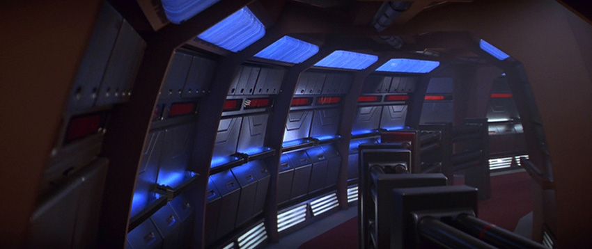
    Basically, assume the centre of the two arcs for the corridors commences at the main door for engineering (and they both share the same arc, ie: one of the two rings is not offset from the other and they both cover each engineering door), the "narrow straight" corridors that you see early on during the engineering attack are the smaller corridors on the edges of the rings where they would be capped by doors or Jefferies tubes. So basically, where each door to engineering exists, there's a corridor that goes full length (but can be capped as shown in certain scenes to conceal them), with the big engineering double door having the 2nd level above it the width of the inner ring and the long corridor going from the double door to a turbolift-like door opposite it at the outer edge of the far ring.

    You can see this in two scenes where one of the attack teams seems to be "Coming out of a door" from off frame with a door beside them, that's one of the straight corridors.

    The second thicker straight corridor used during the retreat/lily+picard walk and the holosuite scene is the central corridor that's full width (ie: same width as each segment of the rings) that heads away from the engineering door, just shot with the engineering door concealed.

    It's a feasible design, I've managed to fit almost everything in (and can draw it up if I have time) the only thing I can't quite figure out is the Jefferies tubes. I know the main set is a tringle with 3 extending segments, but I can't find where the lily/picard/new guinea scene piece would fit, or if the Jefferies tubes were separate from the engineering set and that was a "wild space" piece they climbed into. I'm just going on the relatively ambiguous quote that implies the Jefferies tubes were part of the larger set.
     
  2. Mytran

    Mytran Rear Admiral Rear Admiral

    Joined:
    Aug 5, 2009
    Location:
    North Wales
    Lets have another look at that quote:

    (Eaves & Dillard, Star Trek: The Next Generation Sketchbook The Movies, 1998, Pocket Books, p232)

    First - I think he's either exaggerating or walking very slowly!

    Second - Count's layout sounds feasible, so I'm off watch some FC! ;)
     
  3. Count

    Count Commander Red Shirt

    Joined:
    Mar 12, 2007
    Location:
    Andromeda Galaxy
    Heh, have fun with that, I'll probably be analysing trekcore screenshots again today, I occasionally try to map the design out to see if I can get it right or at least righter. I've used the insurrection/nemesis designs as a rough idea for the layout of the rings and their distance (The engineering scene with Data in FC has the main engineering door open and the long centre corridor is completely visible to the turbolift along with the inner arcs).

    Only thing I can't quite place is the t intersections, they're either at the very ends of the arcs, or closer to the centre (but anywhere apart from the end and they aren't T intersections at all. Unless there's 5 crossovers instead of 3, but the lack of gaps in the ring bulkheads (being long, contiguous walls) implies there's not 5.
     
  4. Mytran

    Mytran Rear Admiral Rear Admiral

    Joined:
    Aug 5, 2009
    Location:
    North Wales
    I viewed the relevant parts of the film and checked the sketches against my original notes made a few years back and have come to the same conclusion as then:

    However, even that bit matches the description (two quarter-circles, two T-junctions). The longer curved section (probably on another stage) is just gravy for extra scenes.
     
  5. Count

    Count Commander Red Shirt

    Joined:
    Mar 12, 2007
    Location:
    Andromeda Galaxy
    There was a long straight section that linked stages 14 and 15 together. but i disagree that this piece could not be part of the set. They did have plugs to seal up certain sections as needed for redresses. What this looks like to me is the outer ring redressed with the hand rail, and the camera is looking inwards from the outermost segment of the ring from right side, facing towards the centre straight corridor/turbolift shaft. As well, the nemesis corridors were built entirely on another stage and looked like a bent L shape (they're in the E-E blueprints from pages back).

    The Nemesis blueprints HAVE to be ignored as the entire set was shrunk and built for stage 18 which is only 2/3 the size of stage 5, so anything from Nemesis is wrong and should not be used in scaling this. Insurrection pieces can be used though as they rebuilt the FC engineering with partial sets.

    Basically that frame you've got is a redressed version of this shot here: http://movies.trekcore.com/gallery/albums/firstcontacthd/firstcontacthd0708.jpg

    here's two examples of the "small" t junction corridors: http://movies.trekcore.com/gallery/albums/firstcontacthd/firstcontacthd0711.jpg

    http://movies.trekcore.com/gallery/albums/firstcontacthd/firstcontacthd0712.jpg

    you can see behind picard the gap in teh corridor where a T goes at the end of the inner ring, this would line up with the above shots where they're walking in from the outer ring as the T would not be able to stay straight and line up with the outer ring unless the walls narrowed: http://movies.trekcore.com/gallery/albums/firstcontacthd/firstcontacthd0717.jpg

    This is probably the inner ring as the corridor is on the wrong side to be outer ring: http://movies.trekcore.com/gallery/albums/firstcontacthd/firstcontacthd0722.jpg

    Here's an example of the long centre corridor with the engineering door plugged: http://movies.trekcore.com/gallery/albums/firstcontacthd/firstcontacthd0742.jpg

    Now they've just walked from the outer ring to the inner one on the set with the engineering door still plugged, notice the larger gap and that the upper level is covered? http://movies.trekcore.com/gallery/albums/firstcontacthd/firstcontacthd0747.jpg

    Now they've just walked into the engineering space, they're standing at the outer ring (notice the recessed turbolift behind them at the edge of the outer ring, like your screenshot?) They're staring into engineering:

    http://movies.trekcore.com/gallery/albums/firstcontacthd/firstcontacthd0759.jpg

    Worf walks in from the borged inner ring and meets them at the junction:

    http://movies.trekcore.com/gallery/albums/firstcontacthd/firstcontacthd0765.jpg

    http://movies.trekcore.com/gallery/albums/firstcontacthd/firstcontacthd0766.jpg

    That one shot alone shows that there's two rings stuck together in one set. I suppose it's entirely possible that Picard/data and co walked in from wild space, but considering the number of starfleet/borg scenes they needed, i doubt they'd constantly redress engineering each time they needed to borg it or not. My theory is in FC, the outer ring was completely starfleet looking (and was swapped out for the escape pod sequence) and the inner ring stayed borg the entire movie, with wild walls being raised as needed to hide the engineering doors. Of course the arguemetn against is those borg panels you see adjacent to the turbolift alcove in those centre corridor scenes, but those pieces have little to no lighting, so i imagine they can easily be slid in and out.

    Here's the INS set as seen in the scene where Geordi and Picard revive data (the main door for engineering is up) https://www.flickr.com/photos/99878876@N02/14144413902/in/set-72157644542637766

    Which was a partial reconstruction missing the outer rings.

    This is the plan that gave me the idea that maybe the two quarter rings are offset and only met in the middle with the centre corridor. Because INS didnt need many corridors, they didn't rebuild the whole thing. Also, teh problem with teh insurrection plans is they have the stage wall to the right of hte enginering space, so full circles wouldn't fit there, that's the problem with using them as a proper reference for the dimensions of the two quarter rings, btu it's clear that there's only one "quarter ring there" and the nemesis sets are just weird: https://www.flickr.com/photos/99878876@N02/13972733919/in/photostream/
     
    Last edited: Oct 10, 2014
  6. Firebird

    Firebird Commodore Commodore

    Joined:
    Apr 23, 2005
    Location:
    On the Cinerama screen, in glorious Technicolor.
    I just dug through my archives, and I came across this beauty:

    [​IMG]

    I found it on some auction site a while ago. It was a part of an auction with some other FC blueprints.
     
  7. Mytran

    Mytran Rear Admiral Rear Admiral

    Joined:
    Aug 5, 2009
    Location:
    North Wales
    That's a lovely find and nicely illustrates the two different types of straight corridor; the 5 sectioned horseshoe frame (with the upper level) and the 3 sectioned square frame (which seems only 6 feet wide, compared to the usual 8 feet of the other horseshoes).

    However, I don't think that diagram is the way that the sets ended up being built, for the simple reason that the longest stretch of curved corridor (used for so many scenes in FC) joins the straight corridor from the other direction, as seen here:

    [​IMG]
    (click for HD. you can see the edges of the square framed corridor in the distance)


    On display in this scene is a door section on the extreme left (where Lily and Picard enter), followed by 5 sections which curve clockwise, then a left turn T-junction, then 2 more clockwise sections before the wall plug. The diagram is almost a mirror of that, or else requires the two straight corridors to swap positions. Finally, those curved corridor sections look too narrow, more like 4 feet than the (roughly) 6 feet they ended up as in the movie.

    For all those reasons I think that the diagram you found is probably an extrapolation of the "official" plan upthread rather than an accurate representation of the final design.

    I'll check out Insurrection later and see if anything more can be gleaned. It's certainly tough to see the area around Engineering with all those Borgified bits!
     
  8. 137th Gebirg

    137th Gebirg Admiral Premium Member

    Joined:
    Aug 31, 2000
    Location:
    Eaten by Cannibals
    Actually, this looks like the junction at the bottom of the inner ring (when looking at the diagram above), where you can see the other corridor further up on the left, which corresponds to the narrow corridor at 90 degrees going out to the left of the set chart. This corridor is on a tight curve and it has to be the inner one.

    Those things taking up space in the hallway always annoyed me.
     
  9. Mytran

    Mytran Rear Admiral Rear Admiral

    Joined:
    Aug 5, 2009
    Location:
    North Wales
    I know, they're not even connected, and they're wonky to boot! What on earth were they supposed to be?

    The square framed straight corridor (peeking out in my screencap) has only 3 segments, so it can't be the one branching out to the left on the diagram in Post #86
     
  10. 137th Gebirg

    137th Gebirg Admiral Premium Member

    Joined:
    Aug 31, 2000
    Location:
    Eaten by Cannibals
    It's possible that most or all of the corridor segments (or at least the walls) were flying walls, and may be moved around and reconfigured as the shot required. The floor plan design is probably considered the "zero point" configuration for the maximum requirements of all possible shots, to be customized later to accommodate special camera angles and such. In short, what we see on paper may not be reflected in its entirety on screen.

    It is curious how that floor plan layout is so much different and bigger from the "official" blueprints, while still maintaining some level of drafting quality without all the extra call-outs.
     
  11. Count

    Count Commander Red Shirt

    Joined:
    Mar 12, 2007
    Location:
    Andromeda Galaxy
    My problem with #86's diagram is that the "straight" corridor is too long in that diagram. It's much shorter as seen in FC (see the screenshots of it I posted earlier) but if you enlarge that and make it another quarter circle in size, it's a reasonably believable layout. And it does match my theory of two quarters offset.

    As for the set redresses, the reason the set was designed with identically sized pieces for the sides was they could wheel in and out the borg pieces in a matter of minutes/hours as opposed to constantly having to break down and rebuild. I remember listening to that explanation in a BTS feature for First contact. Pity there was no demo though.
     
  12. Redgeneral

    Redgeneral Commander Red Shirt

    Joined:
    May 9, 2014
    Location:
    Sol III
  13. Mytran

    Mytran Rear Admiral Rear Admiral

    Joined:
    Aug 5, 2009
    Location:
    North Wales
    I was studying the FC footage again and then I saw this, thanks Redgeneral!
    https://www.flickr.com/photos/99878876@N02/15476094496/in/photostream/

    As usual, I was trying to make things fit from an artistic POV instead of a constrained setbuilder's POV. I'll post my notes tomorrow when it's not so late (UK time).

    Suffice to say that the 5 segmented straight corridor I was trying to place is not where it ought to be if I was constructing a ring corridor in real life!
     
  14. Count

    Count Commander Red Shirt

    Joined:
    Mar 12, 2007
    Location:
    Andromeda Galaxy
    Very nice redgeneral, that first diagram seems to almost complete match the interior of the image from #86. The diagram has a gap in the last segment of the ring in the top left but doesn't actually show it. So I guess that my design was off... by a lot, heh. AT least we have more info now, and that's awesome!

    All we need now is to find where the Jefferies tubes from FC fit in, the triangle junction probably connected to engineering, but the Lily/picard guinea piece is missing and so is the crusher escape sickbay one.

    I do know that that particular piece was a reuse from Star Trek Borg's Righteous Jefferies tubes, so it's possible it was attached to voyager's sickbay on stage 9 for the movie, or it was attached to one of the Jefferies tube access doors in the corridor set.
     
  15. Mytran

    Mytran Rear Admiral Rear Admiral

    Joined:
    Aug 5, 2009
    Location:
    North Wales
    Yep, the big difference is that the straight corridor peeking in at the top of RedGeneral's conclusive pic was significantly reduced in length (and width) compared to the post#86 sketch. Speaking of width, it was a classic "moment of truth" for me when I saw this pic and realised that the standard E-E corridors are a massive 12 feet wide (compared to the 8 feet on previous shows and movies). That explained the oddities I'd mentioned upthread (about the segments seeming to be too short etc). A behind the scenes photo shows the extreme width/height proportions quite nicely, I think.

    Obviously the set builder felt that "bigger" was "more cinematic". However, even those scales were not sufficient, it seems. When filming scenes in Engineering, the floorplan expanded greatly into the areas used by the corridor layout, as can be seen here. The curved line on the floor is the extent of the actual engine room. You can even see the edge of one of the horsehoe corridor frames, over on the right!

    Finally, here is the full quote which mentions the circles, as well as the swappable wall panels:

     
  16. Count

    Count Commander Red Shirt

    Joined:
    Mar 12, 2007
    Location:
    Andromeda Galaxy
    Honestly, I just see that as how engineering is supposed to look and the door the borg lowered was the isolation door for the E-E that Geordi always loved rolling under in TNG eps. Because if you look at it in Insurrection, the door is up as well and engineers spill out into the 2 level corridor thing as well. So I don't think it was a "lack of space in there" as opposed to being there by design.
     
  17. Redgeneral

    Redgeneral Commander Red Shirt

    Joined:
    May 9, 2014
    Location:
    Sol III
    Just one image today...
    https://www.flickr.com/photos/99878876@N02/15518923512/
    (large image requiring "View all sizes")

    I had previously uploaded a scan of the voyager transporter room set plan, but the numbers were very hard to read in places. Using filters and measuring the pixels, I've been able to decipher all but 4 of the measurements. I've written the numbers on top in orange.


    My plan at the moment is to make 3d version (and check the values as I go along).
    Does anyone have images of the side of the transporter room (as shown in orange https://www.flickr.com/photos/99878876@N02/15332536279/). The screen shots I've come across only show the pad and controls, or have this side section blurred.
     
  18. Mytran

    Mytran Rear Admiral Rear Admiral

    Joined:
    Aug 5, 2009
    Location:
    North Wales
    It's not an area that ever got very much focus, from what I recall. It seemed to pop up as a feature more in Nexgen, although I'm not sure how much it was redressed for Voyager.

    Count: What you say is quite possible and there's nothing in FC that would suggest Engineering ends at the huge drop-down wall (quite the opposite in fact, when Picard goes down there alone he passes through quite a few more Borgified corridors after walking through the apparent entry point).
    However, that would make the Insurrection corridor walk scene (just after Data's rescue) a little odd, as they round the corner of a standard corridor and go straight into Engineering past the drop-down wall, as if that was the border of the Engine Room. In additon, Nextgen spent 7 years having to redress the corridor every time they wanted to do a scene in main Engineering, largely due to the Engine Room being almost an afterthought. It strikes me as very odd that a major motion picture would plan such a thing intentionally (odd but not impossible, FWIW). Voyager certainly redesigned the stage to make better use TNG's space soon enough!
     
  19. Count

    Count Commander Red Shirt

    Joined:
    Mar 12, 2007
    Location:
    Andromeda Galaxy
    Mytran, makes sense I suppose. But then again, I can also see it from the perspective of it could also be viewed in First contact as an example of the continued borgifying of the space, if they opened it up further later on, becoming less starfleet-centralized and more borgishly uniform.

    but yea, I do see your point.

    Redgeneral: very nice, unfortunately i don't have anything for that side. that was that really weird minitransporter thing that Voyager had instead of control panels over there. like a half-replicator/half-transporter doodad.

    Nice on the dimensions though. I'd be using the 10" height of the walls to figure out teh doors now, but i'm fairly certain the doors are 6'8" tall and 3 feet wide per door (with 6 for the double doors) based on my previous calculators.
     
  20. Count

    Count Commander Red Shirt

    Joined:
    Mar 12, 2007
    Location:
    Andromeda Galaxy
    Pity the double door width isn't there though. I used the high quality version of the image you downloaded and tried to measure out pixels, assuming that the 7' reference on the wall layout referred to the height of the door is 4" higher then i calculated based on other shots/plans) and the door width comes out anywhere to between 6'6" to 8' in width.

    I think the diagrams are not actually to scale, which makes it a pita to sort things out. But oh well :) Still enough.

    i've been going back over my old stage 9 set that i was building in Maya and tweaking the dimensions now based on what i've learned. Getting door heights alone is more than enough to start extrapolation on other dimensions.
     
    Last edited: Oct 14, 2014