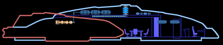
Just getting a few things blocked in so far . . .
 http://i299.photobucket.com/albums/mm309/LCARS24/AS3.png
Last edited:

")
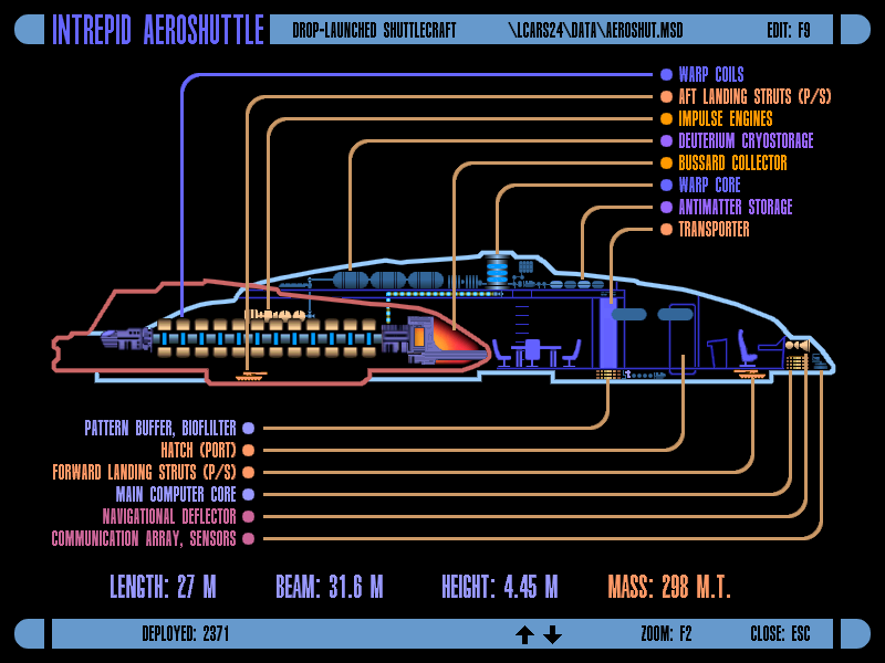
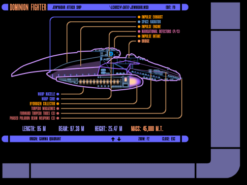
Yeah, but you can see the limited space in the full schematic above. Here are the solutions for three other ships with the same problem. What I could do with this one is make some of the warp coils just outlines to provide a degree of transparency to show the sleeping quarters in the aft section. And I don't want to show the nacelle separately, as seen with the Voyager MSD, since that cuts into space for the callouts.
Danube class
S.S Raven
Saber Class

We use essential cookies to make this site work, and optional cookies to enhance your experience.